
Methods and systems for performing root cause analysis

a root cause and analysis technology, applied in the field of methods and systems for performing root cause analysis, can solve the problems of increasing the complexity of the information technology (it) system of the company, the increasing complexity of the system itself, and the increasing difficulty of budgeting

Active Publication Date: 2009-12-17
HITACHI LTD
View PDF20 Cites 120 Cited by
  • Summary
  • Abstract
  • Description
  • Claims
  • Application Information

AI Technical Summary

Benefits of technology

[0012]Exemplary embodiments of the invention provide solutions which improve the accuracy and reduce the calculation costs associated with a root cause analysis. These and other features and advantages of the present invention will become apparent to those of ordinary skill in the art in view of the following detailed description of the preferred embodiments.

Problems solved by technology

According to recent trends, information technology (IT) systems of companies are becoming ever more large and complex.
However, as mentioned above, IT systems themselves are growing rapidly, while IT budgets are typically becoming more restricted.
This has resulted in each administrator being responsible for managing a very large area of the IT system, and the size of these systems can make it difficult to determine the actual location and “root cause” of a problem that might occur.
For example, some vendors provide root cause analysis products, but these products fail to provide any mechanisms for determining the time range of events to be inputted to the analysis engine.
This means that calculation costs are inefficient and the accuracy of analysis is inadequate.
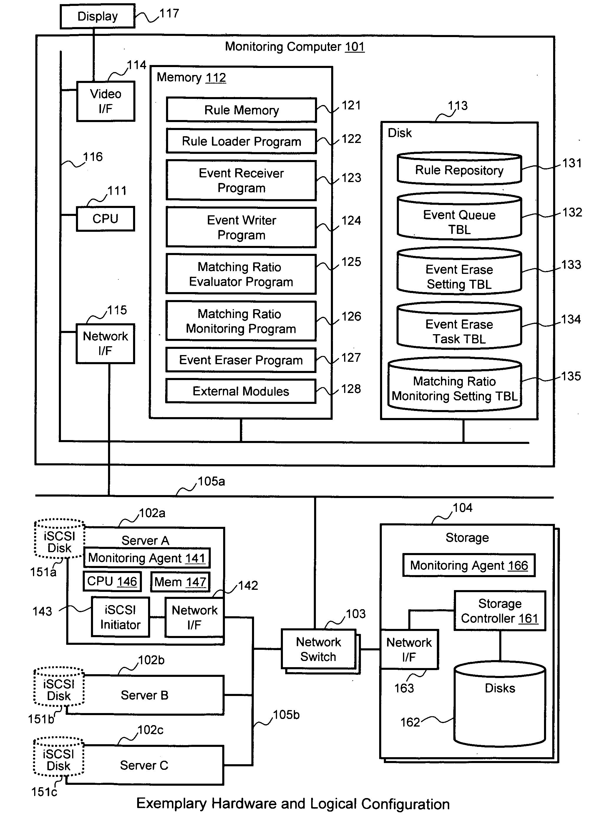
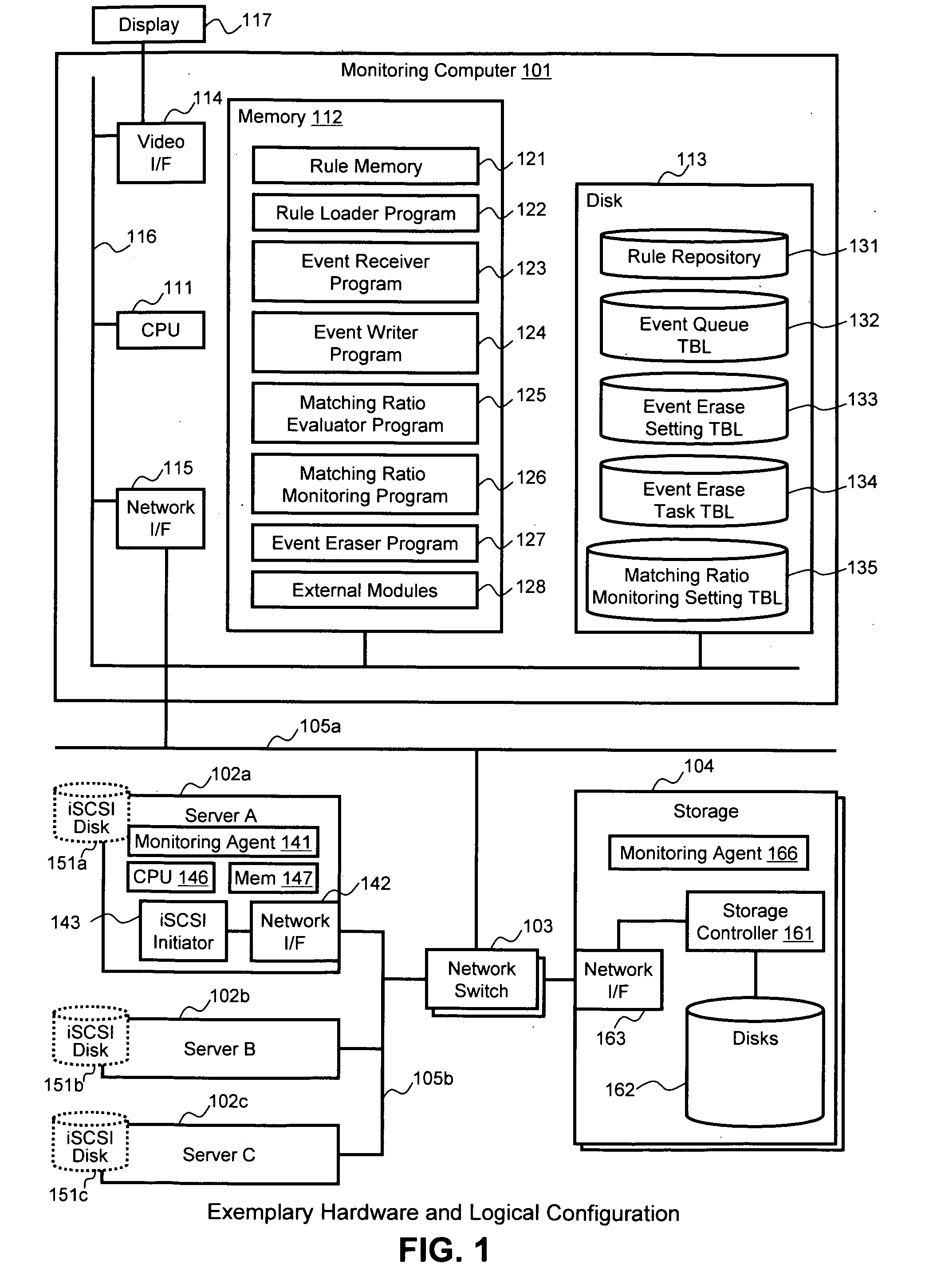
For example, in an information system having a topology made up of a number of different nodes, such as servers, switches, storage systems, and the like, if one of those nodes should cause a failure, error or other occurrence in the system, the failure will affect any other nodes connected to that node in the system topology, and error event messages may be issued to the administrator from a number of different nodes in the IT system.
Thus, in some cases it can be very difficult for an administrator to determine which node in the system is the actual root cause of the errors.
However, CCT fails to provide any mechanisms for determining the time range of events to be inputted to the codebook.
Thus, there is no means for determining correct points in time for generated events.
If the input range for an event is incorrect, then the results that are produced may also be incorrect.
However, CCT analysis is typically carried out including past events whenever an event occurs, and thus, the same event must be processed repeatedly, which can affect accuracy of the analysis and greatly increase the cost of calculating the root cause of an event.
However, in the Rete algorithm, the almost identical rules can be treated as being redundant due to Rete's tree-structured sorting network.

Method used


Image

  • Methods and systems for performing root cause analysis
  • Methods and systems for performing root cause analysis
  • Methods and systems for performing root cause analysis

Examples


Embodiment Construction

[0030]In the following detailed description of the invention, reference is made to the accompanying drawings which form a part of the disclosure, and in which are shown by way of illustration, and not of limitation, exemplary embodiments by which the invention may be practiced. In the drawings, like numerals describe substantially similar components throughout the several views. Further, it should be noted that while the detailed description provides various exemplary embodiments, as described below and as illustrated in the drawings, the present invention is not limited to the embodiments described and illustrated herein, but can extend to other embodiments, as would be known or as would become known to those skilled in the art. Reference in the specification to “one embodiment” or “this embodiment” means that a particular feature, structure, or characteristic described in connection with the embodiment is included in at least one embodiment of the invention, and the appearances of...


PUM


Abstract

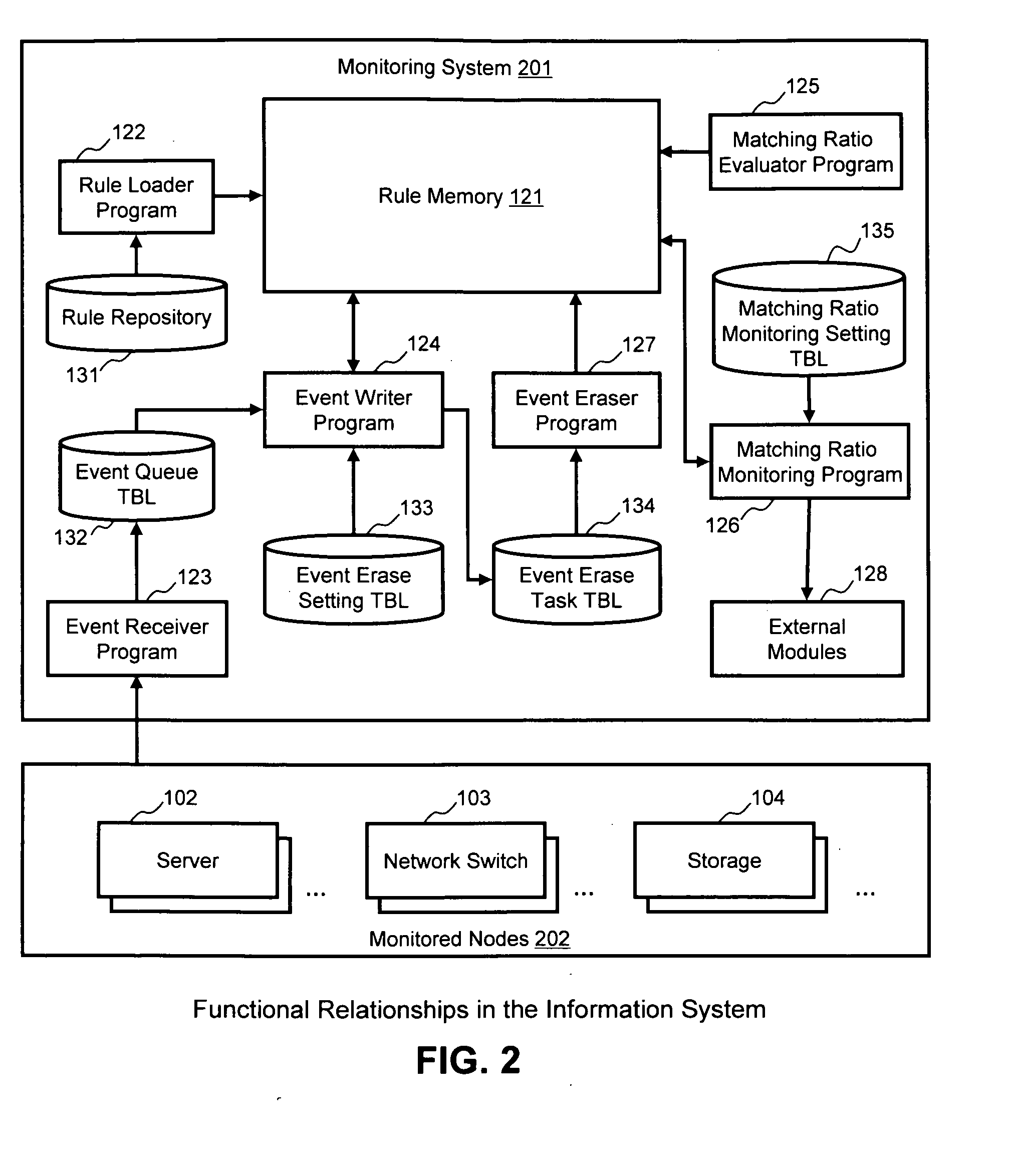
A root cause analysis engine uses event durations and gradual deletion of events to improve analysis accuracy and reduce the number of required calculations. Matching ratios of relevant rules are recalculated every time notification of an event is received. The calculation results are held in a rule memory in the analysis engine. Each event has a valid duration, and when the duration has expired, that event is deleted from the rule memory. Events held in the rule memory can be deleted without affecting other events held in the rule memory. The analysis engine can then re-calculate the matching ratio of each rule by only performing the re-calculation with respect to affected rules related to the deleted event. The calculation cost can be reduced because analysis engine processes events incrementally or decrementally. Analysis engine can determine the most possible conclusion even if one or more condition elements were not true.

Description

BACKGROUND OF THE INVENTION[0001]According to recent trends, information technology (IT) systems of companies are becoming ever more large and complex. For example, in some businesses, the IT system is no longer just an infrastructure of the business, but needs to act in partnership with the business to increase the value and competitiveness of the business. Furthermore, the rapid growth of IT systems is not limited to very large companies, but even mid-sized companies can now have hundreds of servers. In addition, the rapid growth of server virtualization technology is causing an acceleration of this trend.[0002]Despite the recent trends of massive growth in data centers and other IT systems, the administrators of IT organizations are still required to efficiently manage these large and complex IT systems to keep them running properly. When a problem occurs, the administrators need to recognize that there is a problem, analyze the problem, and then resolve the problem as soon as po...

Claims


Application Information

Patent Timeline
IPC IPC(8): G06N5/02
CPCG06F11/0709G06F11/079H04L41/046G06N5/025H04L41/069H04L41/12H04L41/16H04L41/0681H04L41/0631H04L43/04
Inventor KUDO, YUTAKAMASUISHI, TETSUYAFUJITA, TAKAHIROMORIMURA, TOMOHIRO
Owner HITACHI LTD
Learn More