Method to capture and support a 3-D contour

a 3-d contour and support technology, applied in the field of 3d (three-dimensional) contour capture, can solve the problems of not providing an inexpensive, uncomplicated, clean, accurate method for capturing the 3d contour,

Inactive Publication Date: 2009-12-24
TADIN TONY G
View PDF12 Cites 81 Cited by
  • Summary
  • Abstract
  • Description
  • Claims
  • Application Information

AI Technical Summary

Benefits of technology

[0121]Another object of the disclosure is that the insole / midsole includes beads or particles, preferably semi-rigid, to provide the support to all or a portion or portions of the wearer's foot. The insole / midsole includes a base shell support layer, often referred to as a base layer, that has a heel support portion and, depending on the foot length of the insole / midsole, preferably also has any one or combination of arch support portions, that is, a transverse arch support portion, a medial arch support portion, a lateral arch support portion, and a metatarsal arch support portion. In accordance with the disclosure, the base shell support layer preferably is semi-rigid, although it can be flexible or rigid. The particles can be disposed directly or indirectly on the heel support portion, to support the heel, or to form, support, adapt or customize the any one or combination of the aforementioned arch support portions. The particles can form the anatomical arch support contour or they can approach, be adjacent, or partly or fully cover a, e.g., molded-in, domed, arch support. Generally, given a sufficient thickness, the more rigid the base layer, the less the need for support of anatomical contouring with particles or otherwise.

Problems solved by technology

However, the heretofore 3D capture systems do not provide an inexpensive, uncomplicated, clean, and accurate methodology for capturing the 3d contour of a subject item.

Method used


Image

  • Method to capture and support a 3-D contour
  • Method to capture and support a 3-D contour
  • Method to capture and support a 3-D contour

Examples


Embodiment Construction

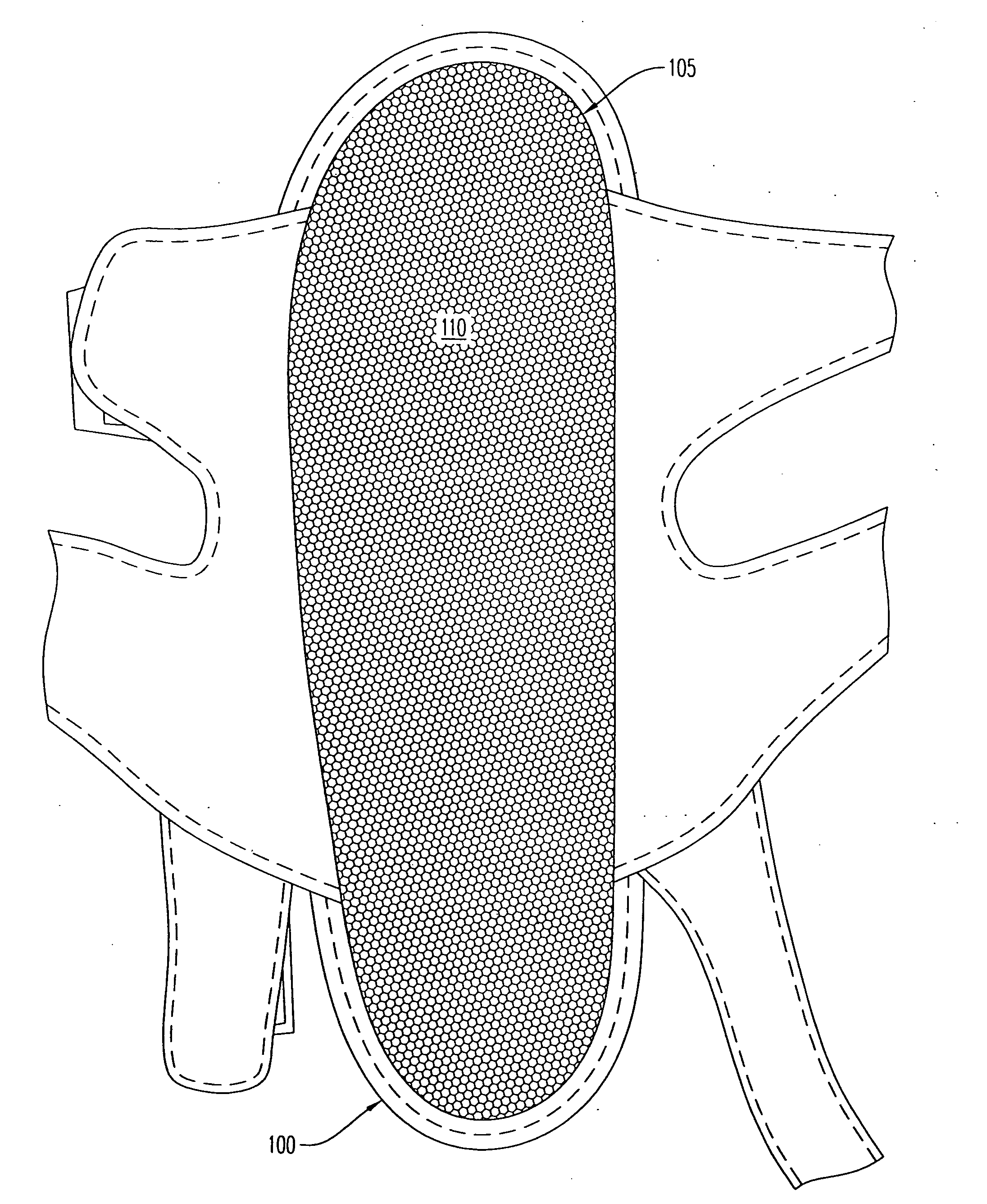
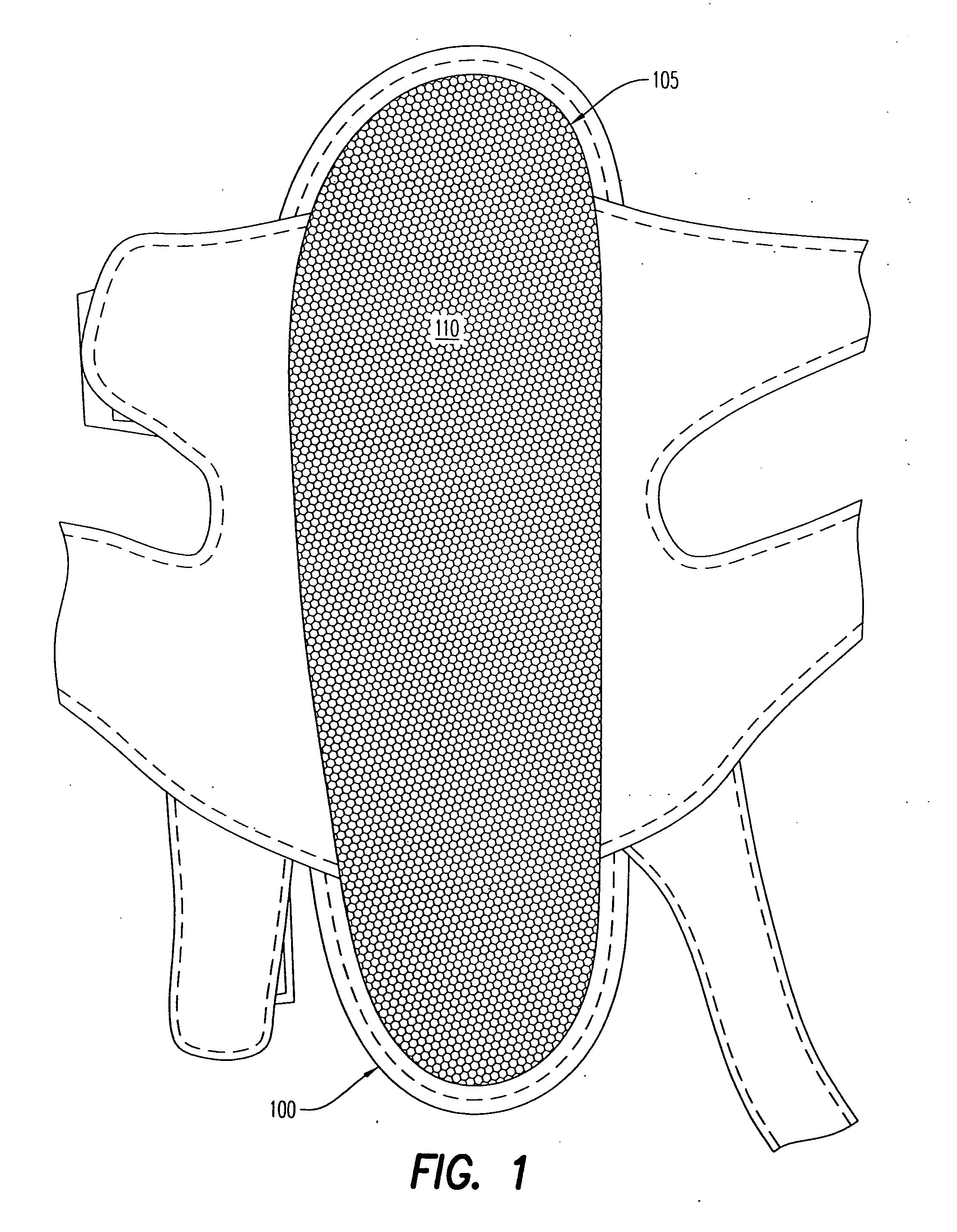
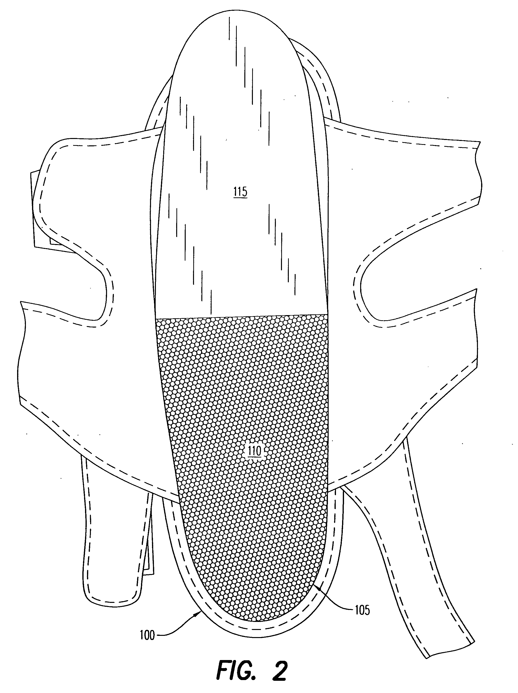
[0284]A three dimensional capture system including a substantially air-tight housing is provided. The shape of the housing is preferably flexible and compatible with the size and shape of a subject item for which a 3-D contour is to be measured. The housing defines a reservoir therein. Loose particles and a gas and / or a liquid are disposed in the reservoir. A valve system is disposed in communication with the reservoir.

[0285]In the instance the housing has a sufficient volume of the air and / or liquid inside of the reservoir allowing free movement of the particles therein, the container can be bent, formed or shaped at will. In the instance the housing is bent, formed or otherwise has attained a desired shape, then all or most of the gas and / or liquid inside the reservoir is removed via the valve system. Removal of the gas and / or liquid from the reservoir forces the loose particles in the housing into close proximity to one another. This close proximity of the loose particles prevent...


PUM

PropertyMeasurementUnit
angleaaaaaaaaaa
heightaaaaaaaaaa
sizeaaaaaaaaaa

Abstract

An insole for placement in or on an article of footwear to support all or a portion of a wearer's foot, comprising: a base shell support layer having an upper surface, wherein the base layer includes a heel support portion, a plurality of substantially rigid particles disposed on the heel support portion, and an upper layer, the upper layer overlying and being secured to the base layer, the upper layer overlying the particles and maintaining them in an area between the upper layer and the base layer.

Description

CROSS-REFERENCE TO RELATED APPLICATIONS[0001]The present application is claiming priority of U.S. Provisional Patent Application Ser. No. 60 / 511,015, filed on Oct. 14, 2003, U.S. Provisional Patent Application Ser. No. 60 / 535,773, filed on Jan. 12, 2004, U.S. Provisional Patent Application Ser. No. 60 / 549,248, filed on Mar. 2, 2004, and U.S. patent application Ser. No. 10 / 965,666, filed on Oct. 14, 2004, the entire contents of each of which are herein incorporated by reference.BACKGROUND OF THE INVENTION[0002]1. Field of the Invention[0003]This invention relates to 3-D (three-dimensional) contour capturing and, more particularly, to a method and system for capturing and supporting a 3D contour of a subject object.[0004]2. Description of the Related Art[0005]In the prior art there are various known methods for capturing a 3D contour. However, the heretofore 3D capture systems do not provide an inexpensive, uncomplicated, clean, and accurate methodology for capturing the 3d contour of...

Claims


Application Information

Patent Timeline
Patent Type & Authority Applications(United States)
IPC IPC(8): A43B7/22A43B7/16A43B13/38A43B23/28B32B3/08A43B7/14A43B7/18
CPCA43B3/0005A43B7/28B32B5/26A43B17/035B32B3/08A43B13/203B32B5/16B32B5/24B32B5/30B32B7/12B32B27/12B32B27/14B32B27/32B32B3/266B32B2255/02B32B2255/04B32B2255/20B32B2264/0221B32B2307/21B32B2437/02Y10T428/249975Y10T428/249986A43B3/34
Inventor TADIN, TONY G.
Owner TADIN TONY G
Why Eureka
Try Eureka