
Plug-in-piston assembly and method of using the same

a technology of plug-in pistons and assembly methods, which is applied in the direction of spark plug ignition, combustion engines, machines/engines, etc., can solve the problems of wasting fuel and energy, generating higher than normal levels of pollution, and burning is not yet completed, so as to reduce fuel consumption and exhaust emissions, increase output power, and accelerate faster

Inactive Publication Date: 2009-12-24
RUSSELL ENERGY CORP
View PDF13 Cites 13 Cited by
  • Summary
  • Abstract
  • Description
  • Claims
  • Application Information

AI Technical Summary

Benefits of technology

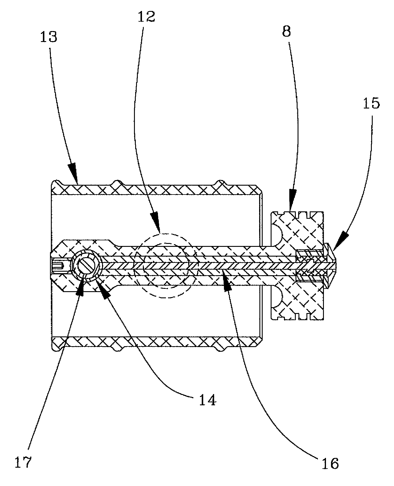
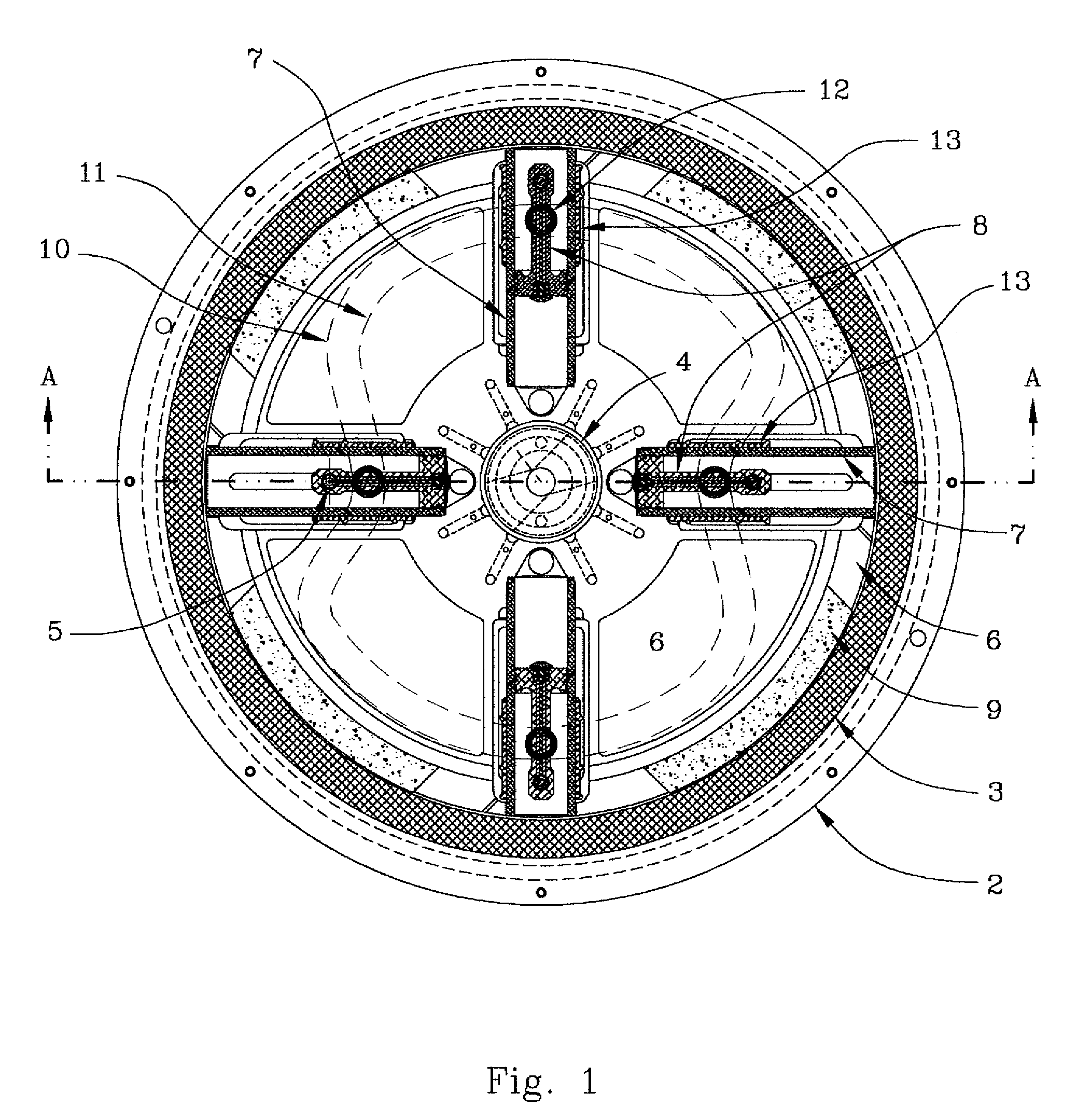
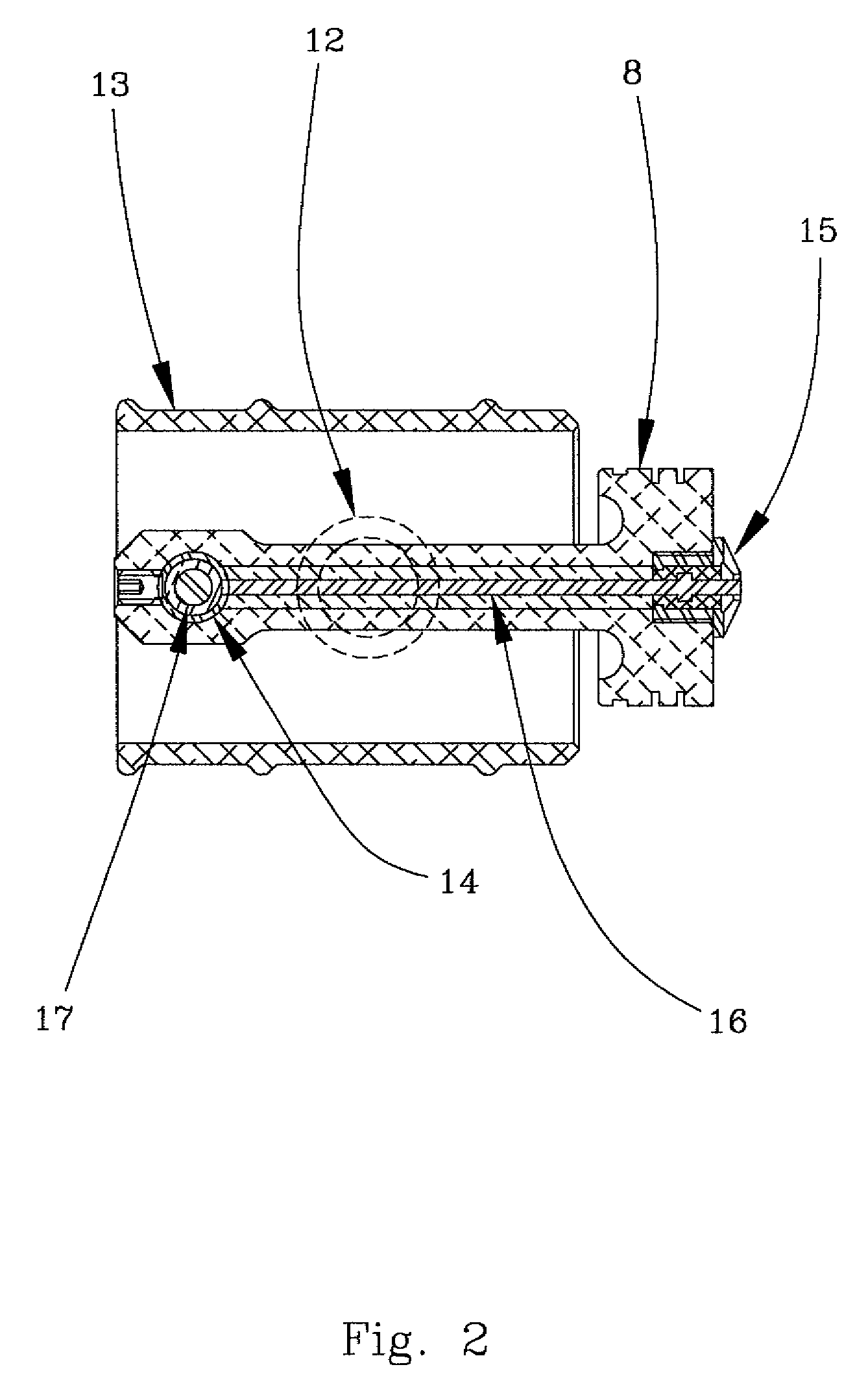
[0004]In contrast to conventional internal combustion engine configurations where the spark plug is located in the stationary engine head, the present invention provides a combined piston and spark plug configuration, hereinafter referred to as plug-in-piston assembly, where the spark plug is attached to and moves in unison with the piston. By initiating the combustion burn from the piston face, as is the purpose of the plug-in-piston design, the burn will now emanate from the movable piston face at a time when the piston is relatively stationary and be directed towards the stationary head of the engine allowing the flame to more completely consume all of the fuel in the cylinder prior to the opening of the exhaust valve. This single action will allow much higher acceleration rates for the piston while providing more complete combustion of the air-fuel mixture increasing output power while reducing fuel consumption and exhaust emissions.
[0011]Yet another intention of certain aspects of the present invention may be to provide a plug-in-piston assembly that allows for a higher and more complete consumption of fuel when compared to a conventional internal combustion engine where the spark plug is located in the stationary engine head.
[0012]A further intention of at least one aspect of the present invention may be to provide a plug-in-piston assembly that provides increased power output with reduced fuel consumption when compared to a conventional internal combustion engine where the spark plug is located in the stationary engine head.
[0013]Still another intention of certain aspects of the present invention may be to provide a plug-in-piston assembly that produces fewer pollutants as a result of improved combustion when compared to a conventional internal combustion engine where the spark plug is located in the stationary engine head.
[0014]Another intention of at least one aspect of the present invention may be to provide a plug-in-piston assembly that can energize the spark plug while it is in motion with the piston.
[0015]A further intention of certain aspects of the present invention may be to provide a plug-in-piston assembly that energizes the spark plug while it is in motion with the cylinder.

Problems solved by technology

When this happens the burn is not yet completed when the exhaust valve opens and the unburned fuel is then expelled into the atmosphere wasting fuel and energy as well as producing higher than normal levels of pollution.

Method used


Image

  • Plug-in-piston assembly and method of using the same
  • Plug-in-piston assembly and method of using the same
  • Plug-in-piston assembly and method of using the same

Examples


Embodiment Construction

[0025]A preferred embodiment of a combined piston and spark plug configuration where the spark plug is threadably attached to and moves in unison with the piston will now be described. Although the preferred embodiment provides for the spark plug being threadably attached to the piston, various other conventional means for attaching the spark plug to the piston are acceptable.

[0026]In a preferred embodiment disclosed herein, the unitary piston body has an integral connecting rod and an enlarged end at the back or the end opposite of the piston face that is receptive of a transverse wrist pin. A hole is bored and threaded in the face of the piston and on the centerline of the piston to receive the spark plug. An additional hole is bored on the centerline of and through the integral piston connecting rod from the back of the spark plug seat to the transverse bore in the back of the piston provided to receive the transverse wrist pin. This hole through the core of the piston is provide...


PUM


Abstract

The combination of a piston with an integrated spark plug to be used in an internal combustion engine is disclosed. The plug-in-piston configuration allows for maximum combustion and fuel efficiency as well as increased power output. Further, the configuration minimizes the release of unburned fuel and pollutants into the atmosphere. A method is also disclosed by which electrical energy is communicated to a spark plug.

Description

BACKGROUND OF THE INVENTION[0001]This invention relates generally to internal combustion engines and, more particularly, to an improved combustion environment within the cylinders in rotary engines employing reciprocating pistons.[0002]In the familiar internal combustion engine, as well as in the familiar rotary piston type internal combustion engine, the spark plug is typically located in the stationary head of the engine. This configuration provides for the ignition of an air-fuel mixture within the cylinder at the point of the spark plug. The ignition of these gasses can be best described as a rapid burn originating at the point of the spark plug and growing out from that point towards the outward moving piston face. During high-speed operation the speed of the piston can exceed the speed of the burn. When this happens the burn is not yet completed when the exhaust valve opens and the unburned fuel is then expelled into the atmosphere wasting fuel and energy as well as producing ...

Claims


Application Information

Patent Timeline
Patent Type & Authority Applications(United States)
IPC IPC(8): F02P13/00
CPCF02P15/04F02P13/00
Inventor RUSSELL, ROBERT L.
Owner RUSSELL ENERGY CORP
Learn More