Wireless power transfer system, power transmitter, and rectenna base station

a power transfer system and transmitter technology, applied in the field of wireless power transfer systems, can solve the problems of degrading whole power generation efficiency, increasing facilities, and increasing circuit scale, and achieve the effect of suppressing the increase in circuit scale and increasing the power value of the received microwav

Active Publication Date: 2009-12-24
MITSUBISHI ELECTRIC CORP
View PDF13 Cites 262 Cited by
  • Summary
  • Abstract
  • Description
  • Claims
  • Application Information

AI Technical Summary

Benefits of technology

[0007]It is therefore an object of the invention to provide a wireless power transfer system, a power transmitter, and a rectenna base station capable of more efficiently making uniform phases of microwaves transmitted from transmitters when the microwaves are received in the rectenna base station without incurring an increase in the circuit scale.
[0009]According to another embodiment of the present invention, there is provided a rectenna base station which receives and combines a microwave transmitted from each of a plurality of power transmitters to generate power. The rectenna base station includes: a rectenna which receives the microwave; a pilot signal transmission antenna which transmits a pilot signal to the power transmitters; and a phase monitor and control section which specifies an identification code for identifying each of the power transmitters and generates a command signal to change a phase of the power transmitter identified by the identification code so as to increase a power value received at the rectenna.
[0011]According to the above configuration, the rectenna base station specifies the identification code of the power transmitter and generates a phase change command signal so as to increase the power value of the received microwave, and if the identification code specified in the command signal matches the identification code of the power transmitter, the power transmitter changes the phase of the microwave to be transmitted, so that an increase in the circuit scale can be suppressed. Additionally, the command signal is superposed on a pilot signal for transmission, so that the command signal reception system of the power transmitter can be implemented using the pilot signal reception system.

Problems solved by technology

According to the wireless power transfer system described in JP-A-2005-319853, the ground rectenna base station needs a circuit for executing spread spectrum modulation of the pilot signal to be transmitted and executing inverse spread spectrum demodulation of the received pilot reply signal and a circuit for comparing the phases of the pilot reply signals for each satellite provided by executing the inverse spread spectrum modulation and feeding back to match the phases and involves a problem of an increase in the facilities.
Each satellite in orbit also needs a circuit for executing inverse spread spectrum demodulation of the pilot signal and executing spread spectrum modulation of the pilot reply signal for generation and involves a problem of an increase in the circuit scale; in addition, power for driving the circuitry becomes necessary and a part of power generated by photoelectric conversion is consumed by the circuit involved in the pilot signal and the whole power generation efficiency is degraded; this is also a problem.

Method used


Image

  • Wireless power transfer system, power transmitter, and rectenna base station
  • Wireless power transfer system, power transmitter, and rectenna base station
  • Wireless power transfer system, power transmitter, and rectenna base station

Examples


first embodiment 1

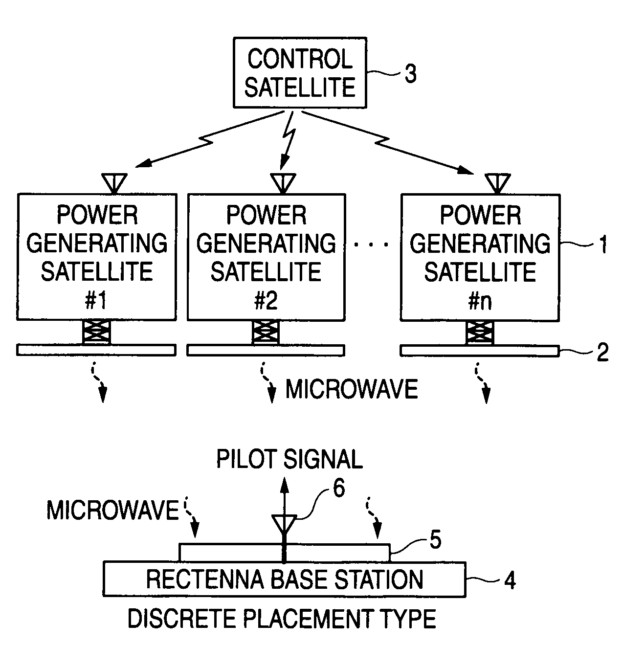
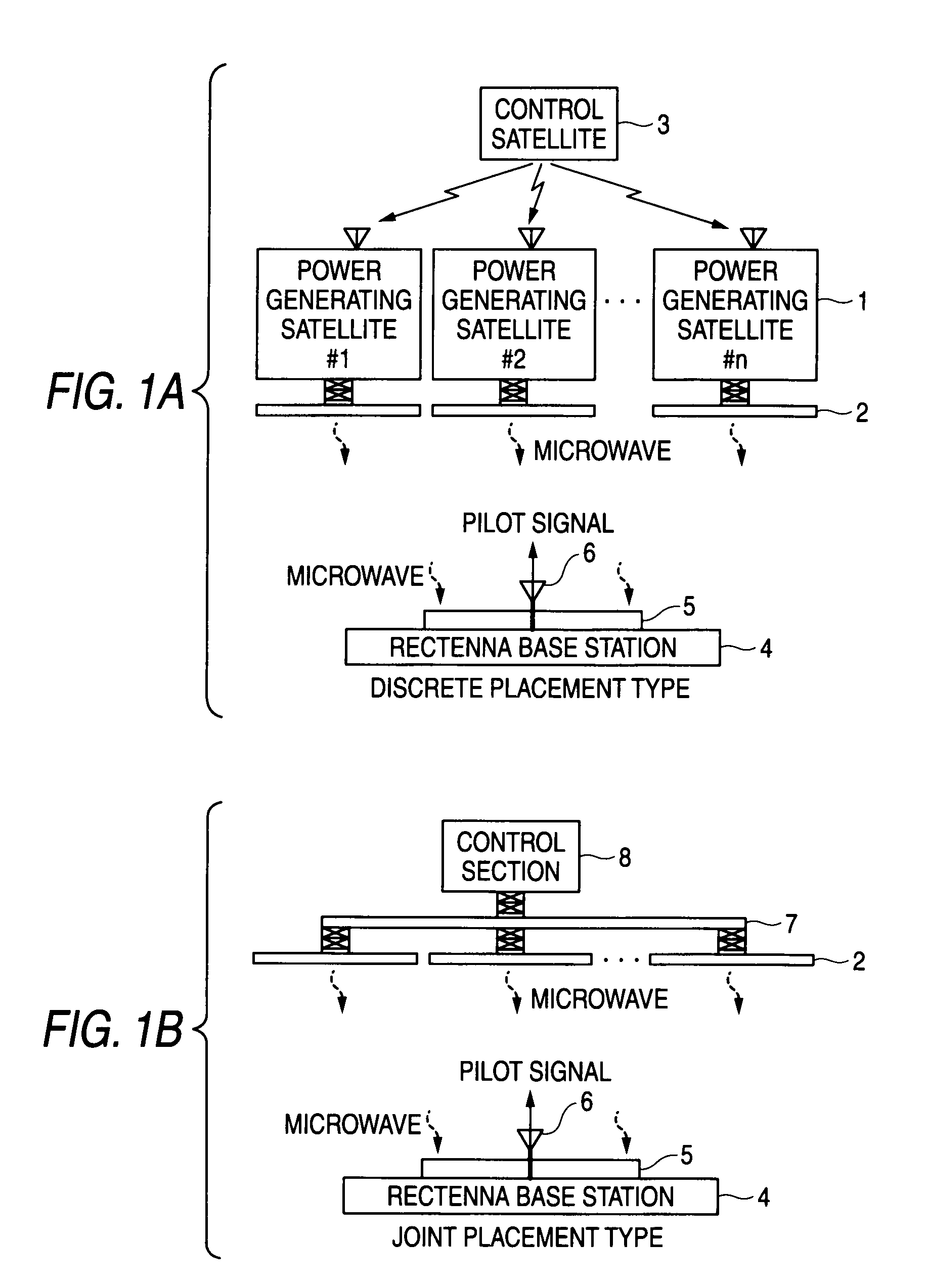
[0023]A wireless power transfer system, a power transmitter, and a rectenna base station according to a first embodiment of the invention will be discussed with FIGS. 1A to 6. FIGS. 1A and 1B are configuration drawings of the wireless power transfer system according to the first embodiment of the invention; FIG. 1A represents the case where a microwave is transmitted from power transmitters provided in discretely placed power generating satellites and FIG. 1B represents the case where a microwave is transmitted from power transmitters joined mechanically. The transmission unit containing the power transmitter in FIG. 1B can be placed in space, on the earth, in the stratosphere, etc. In FIG. 1A, numeral 1 denotes a power generating satellite for receiving sunlight, executing photoelectric conversion of the sunlight to generate power, and transmitting the power with a microwave, and numeral 2 denotes a power transmitter provided in each of the power generating satellites 1. Numeral 3 ...

second embodiment

[0033]A wireless power transfer system, a power transmitter, and a rectenna base station according to a second embodiment of the invention will be discussed with FIG. 7. The power transmitter and the rectenna base station according to the second embodiment of the invention have the configurations and the functions equal to those previously described with reference to FIGS. 3 to 5 in the first embodiment. A processing sequence for performing phase adjustment of the power transmitters in the second embodiment different from that in the first embodiment will be discussed based on FIG. 7.

[0034]FIG. 7 is a flowchart to show a processing sequence for performing phase adjustment of the power transmitters according to the second embodiment of the invention. This processing is performed by a phase monitor and control section 26 of the rectenna base station 4. It is also assumed in the processing flow that the number of the power transmitters 2 is n. At step S8, the phase monitor and control ...

third embodiment

[0038]A wireless power transfer system, a power transmitter, and a rectenna base station according to a third embodiment of the invention will be discussed with FIGS. 9 and 10. The rectenna base station according to the third embodiment of the invention transmits a phase change command over a communication line and acquires power information of a power transmitter 2 over a communication line. FIG. 9 is a functional block diagram to show the configuration of the rectenna base station 4 according to the third embodiment of the invention, and FIG. 10 is a functional block diagram to show the configuration of the power transmitter 2 according to the third embodiment of the invention. In FIG. 9, numeral 31 denotes a command transmitter for transmitting a command signal, numeral 32 denotes a diplexer, numeral 33 denotes a communication line transmission-reception antenna, and numeral 34 denotes a pilot signal transmission section for transmitting a pilot signal. Circuits and parts identic...


PUM


Abstract

A wireless power transfer system includes: a plurality of power transmitters, each of which transmits a microwave; and a rectenna base station which receives the microwave to generate power. The rectenna base station includes: a rectenna; and control section which specifies an identification code for identifying each power transmitter and generates a command signal to change a phase of the power transmitter specified by identification code so as to increase a power value received at the rectenna. Each of the power transmitters comprises: a plurality of transmission antenna elements, each of which transmits the microwave to the rectenna base station; and a phase controller which makes phase change of the microwave based on the command signal from the phase monitor and control section of the rectenna base station if the identification code matches a stored identification code.

Description

CROSS-REFERENCE TO RELATED APPLICATIONS[0001]This application is based upon and claims the benefit of priority from Japanese Patent Application No. 2008-161472, filed Jun. 20, 2008, the entire contents of which are incorporated herein by reference.BACKGROUND OF THE INVENTION[0002]1. Field of the Invention[0003]This invention relates to a wireless power transfer system for receiving sunlight, executing photoelectric conversion of the sunlight to generate power, transmitting a microwave generated based on the power from a plurality of transmitters, receiving the microwave by a receiver, and generating power, and a power transmitter and a rectenna base station used in the wireless power transfer system.[0004]2. Description of the Related Art[0005]For example, JP-A-2005-319853 describes a related-art wireless power transfer system for executing power transfer with a microwave from a power generating satellite placed on orbit in space to a ground receiver. In the related-art wireless pow...

Claims


Application Information

Patent Timeline
Patent Type & Authority Applications(United States)
IPC IPC(8): H02J17/00B64G3/00H01Q21/06H04B7/06H04B7/19
CPCB64G1/428B64G1/443H02J17/00H01Q1/248H01Q3/2605B64G1/66Y10S136/292H02J50/27H02J50/40
Inventor YAMAMOTO, ATSUSHISATO, HIROYUKIIKEMATSU, HIROSHINAMURA, KOJI
Owner MITSUBISHI ELECTRIC CORP
Why Eureka
Try Eureka