Photovoltaic Circuit
a photovoltaic circuit and photovoltaic technology, applied in secondary cell servicing/maintenance, safety/protection circuits, batteries, etc., can solve the problems of poor solar energy efficiency and charging efficiency, and achieve the effect of preventing damage to control modules and reducing current power
- Summary
- Abstract
- Description
- Claims
- Application Information
AI Technical Summary
Benefits of technology
Problems solved by technology
Method used
Image
Examples
first embodiment
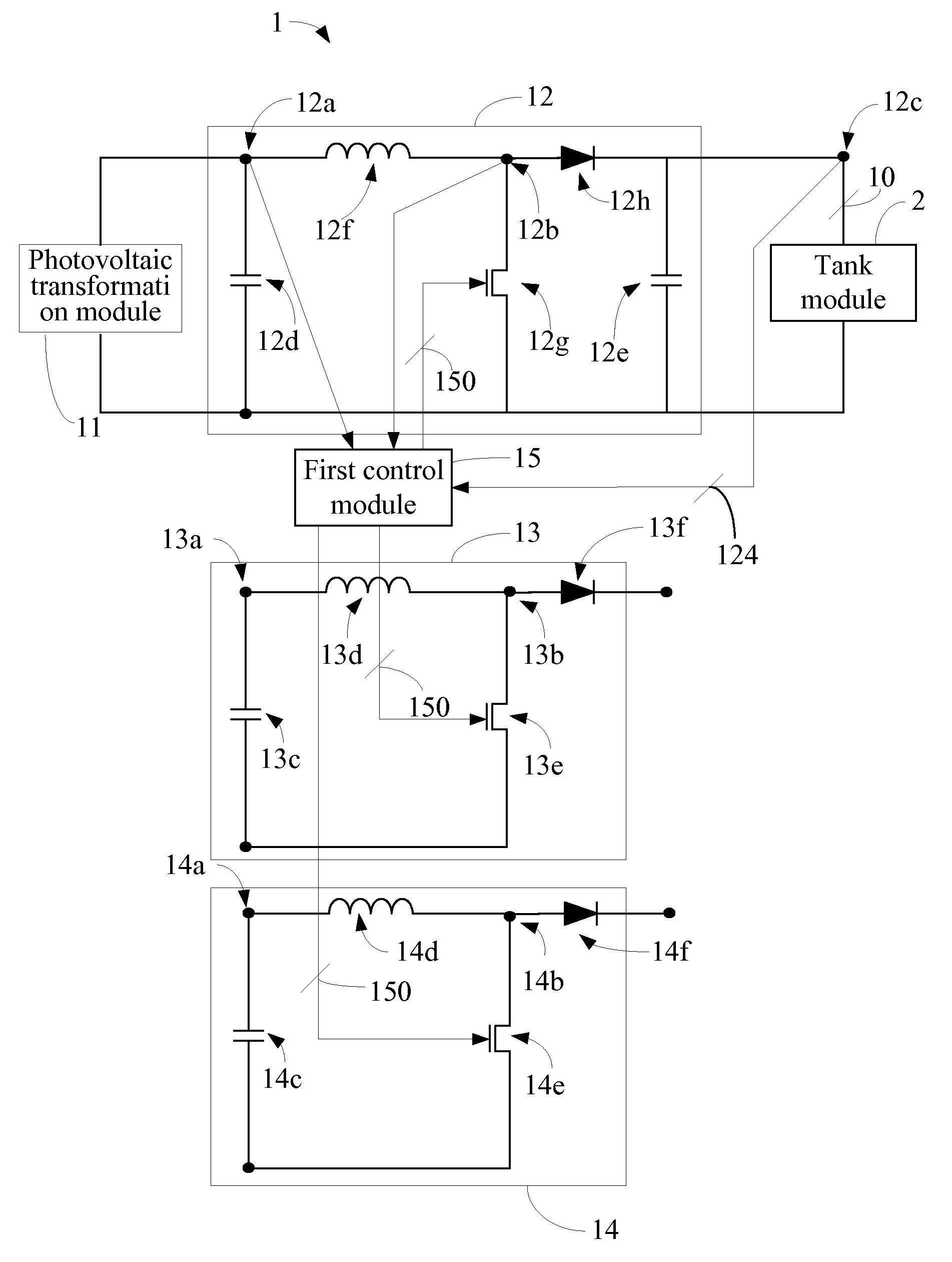
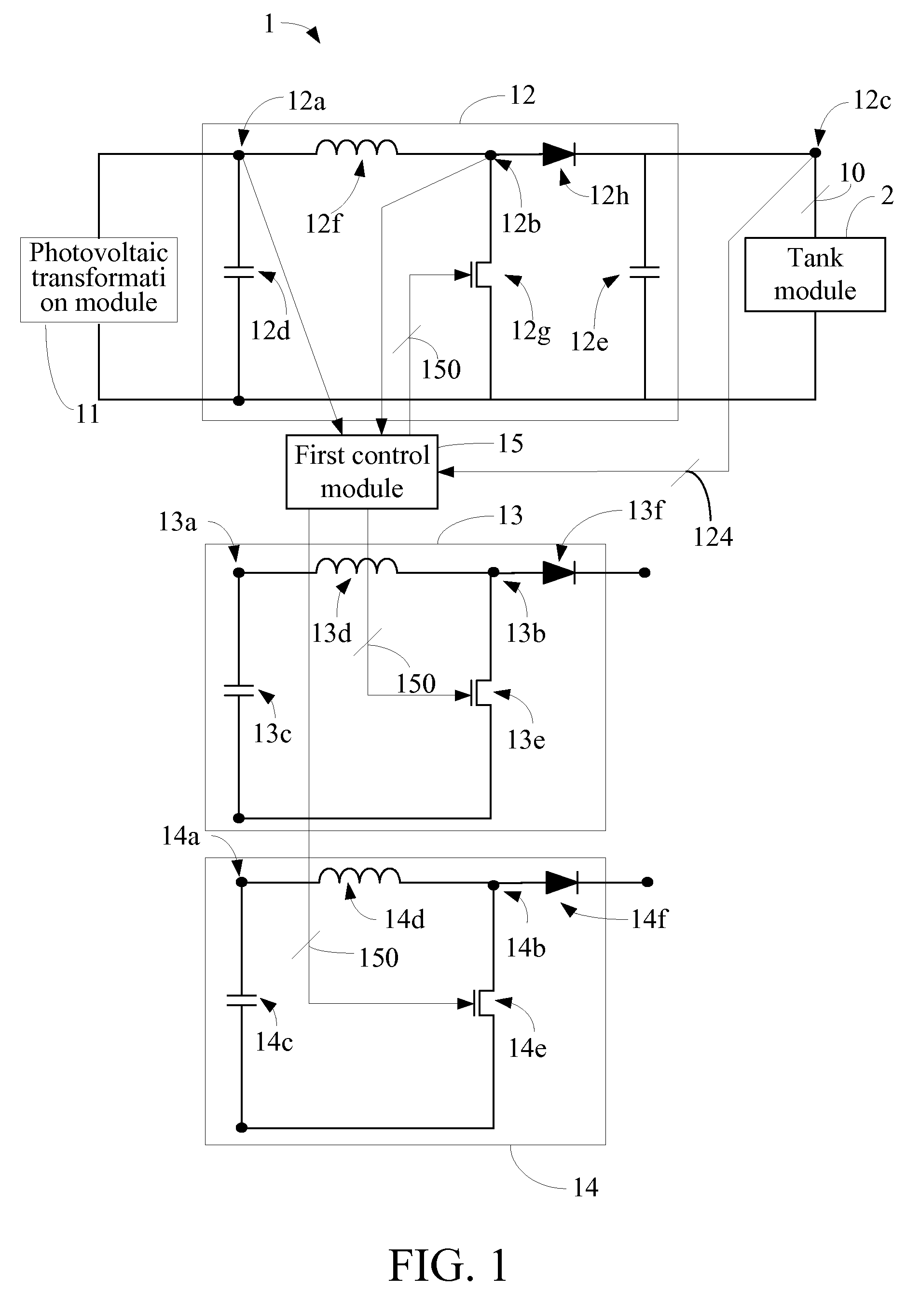
[0030]the present invention is illustrated in FIG. 1, which is a schematic view of a photovoltaic circuit 1. The photovoltaic circuit 1 is coupled to a tank module 2 and a photovoltaic transformation module 11. The photovoltaic transformation module 11 is configured to receive an optical energy and transform the optical energy into a current. The photovoltaic circuit 1 is configured to receive and modulate the current into an output current 10 to be supplied to the tank module 2. The photovoltaic circuit 1 comprises a first process module 12, a plurality of second process modules (i.e., a second process module 13 and a second process module 14 in this preferred embodiment) and a first control module 15. It should be noted that, the number of the second process modules is not intended to limit the present invention; and in other embodiments, another number of the second process modules may be used.
[0031]The first process module 12, which is coupled between the photovoltaic transforma...
second embodiment
[0046]the present invention is illustrated in FIG. 4, which is a schematic view of a photovoltaic circuit 4. Hereinafter, only differences between the photovoltaic circuit 5 and the photovoltaic circuit 4 will be described, and identical portions of the photovoltaic circuit 5 and the photovoltaic circuit 4 are omitted herein.
[0047]The photovoltaic circuit 5 differs from the photovoltaic circuit 4 in that the first process module 12 is connected to the first photovoltaic transformation module 50, and the second processing modules 13, 14 are connected to the second photovoltaic transformation modules 51, 52 respectively. The functions will be readily appreciated by those skilled in the art and thus will not be further described herein.
third embodiment
[0048]the present invention is illustrated in FIG. 5, which is a schematic view of a photovoltaic circuit 6. The photovoltaic circuit 6 is coupled to a tank module 2 and a photovoltaic transformation module 11. The photovoltaic transformation module 11 is configured to receive an optical energy and transform the optical energy into a current. The photovoltaic circuit 6 is configured to receive and modulate the current into an output current 60 to be supplied to the tank module 2. The photovoltaic circuit 6 comprises a first process module 63, a plurality of second process modules (i.e., a second process module 65 and a second process module 67 in this preferred embodiment) and a first control module 15. It should be emphasized that, the number of the second process modules is not intended to limit scope of the present invention, and in other embodiments, another number of the second process modules may be used.
[0049]The first process module 12, which is coupled to the photovoltaic t...
PUM
 Abstract
Description
Claims
Application Information
 - R&D
- Intellectual Property
- Life Sciences
- Materials
- Tech Scout
- Unparalleled Data Quality
- Higher Quality Content
- 60% Fewer Hallucinations
Browse by: Latest US Patents, China's latest patents, Technical Efficacy Thesaurus, Application Domain, Technology Topic, Popular Technical Reports.
© 2025 PatSnap. All rights reserved.Legal|Privacy policy|Modern Slavery Act Transparency Statement|Sitemap|About US| Contact US: help@patsnap.com


