Patient device having an antenna array with polarization diversity

a patient device and antenna array technology, applied in the field of patient devices having antenna arrays with polarization diversity, can solve the problem of additional power consumption to be expended

Active Publication Date: 2009-12-24
BIOTRONIK SE & CO KG
View PDF5 Cites 1 Cited by
  • Summary
  • Abstract
  • Description
  • Claims
  • Application Information

AI Technical Summary

Benefits of technology

[0018]The E-field antenna and/or the H-field antenna can be connected with the transmitter/receiver device by way of a directional coupler. The directional coupler is configured to output a measurement signal to the controller. In this connection, the

Problems solved by technology

Since electro-medical implants can only be replaced by means of an operation, and therefore are supposed to remain in the patient's body for multiple ye

Method used


Image

  • Patient device having an antenna array with polarization diversity
  • Patient device having an antenna array with polarization diversity
  • Patient device having an antenna array with polarization diversity

Examples


Embodiment Construction

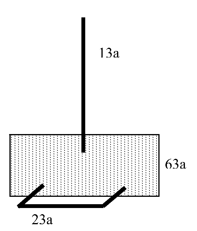
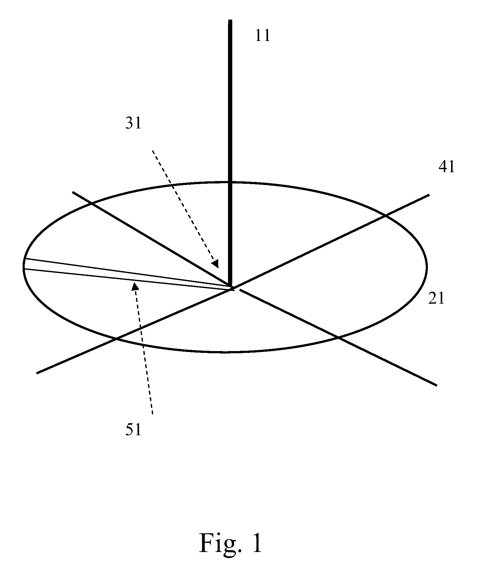
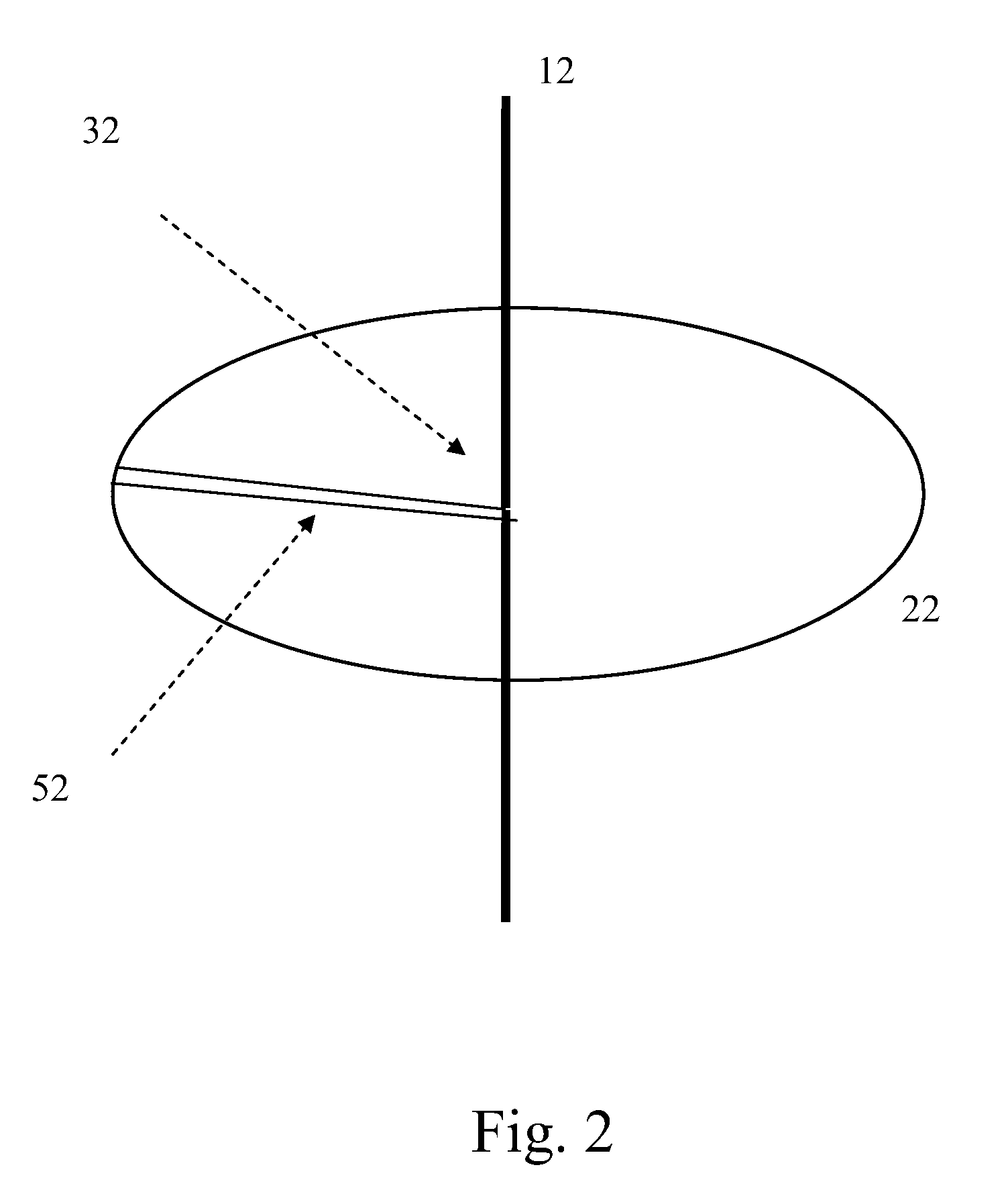
[0026]FIG. 1 shows the antenna array of a first exemplary embodiment of the patient device according to the invention. An E-field antenna 11, which is preferably structured as an electrically lengthened quarter-wave or helical antenna, is disposed in the center of a circular frame antenna 21, in such a manner that the feed point 31 of the E-field antenna is positioned in the center of the frame antenna 21. The frame antenna 21 can generally be structured also as a loop antenna, which then has two or more spirals. Of course, the frame antenna 21 can also assume other geometrical shapes, such as rectangular, square, triangular, or hexagonal. An antenna counterweight 41 is configured as a right-angle cross of two rigid metallic conductors, the intersection point of which is situated as close as possible to the feed point 31 of the E-field antenna 11, on the side facing away from the E-field antenna 11. The metallic conductors are electrically connected with the ground line to the feed ...


PUM


Abstract

A patient device that possesses a receiver array having particularly great reception sensitivity. The patient device possesses an E-field antenna and an H-field antenna, in each instance, where the H-field antenna is structured as a frame antenna. According to the invention, a main axis that runs through the E-field antenna forms an angle of less than 30 degrees to a normal line of an area generated by the frame antenna.

Description

[0001]This application takes priority from German Patent Application DE 10 2008 002 587.9, filed 23 Jun. 2008, the specification of which is hereby incorporated herein by reference.BACKGROUND OF THE INVENTION[0002]1. Field of the Invention[0003]The invention relates to a patient device having an antenna array with polarization diversity.[0004]2. Description of the Related Art[0005]In the medical technology sector, what are called patient devices are increasingly being used, which can be carried along by the patient and usually receive medical or technical data from an implant, such as a heart pacemaker of a patient, for example, at regular intervals, by way of a wireless data connection, and keep these data available for monitoring by the physician, or transmit them directly to a suitable device, for medical monitoring. Since electro-medical implants can only be replaced by means of an operation, and therefore are supposed to remain in the patient's body for multiple years, operated...

Claims


Application Information

Patent Timeline
IPC IPC(8): H01Q1/12
CPCA61B5/0031A61N1/37229H01Q1/242H01Q1/362H01Q21/24H01Q9/16H01Q9/30H01Q9/38H01Q7/00
Inventor MERLIN, JULIAN
Owner BIOTRONIK SE & CO KG
Why Eureka
Try Eureka