Magnetic disk for thermally assisted magnetic recording and magnetic disk applying the same therein
a magnetic recording and thermally assisted technology, applied in the field of magnetic disks, can solve problems such as deteriorating sliding of magnetic disks, and achieve the effect of improving the heating efficiency of the recording layer
- Summary
- Abstract
- Description
- Claims
- Application Information
AI Technical Summary
Benefits of technology
Problems solved by technology
Method used
Image
Examples
embodiment 1
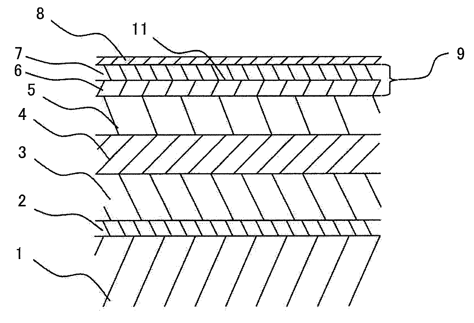
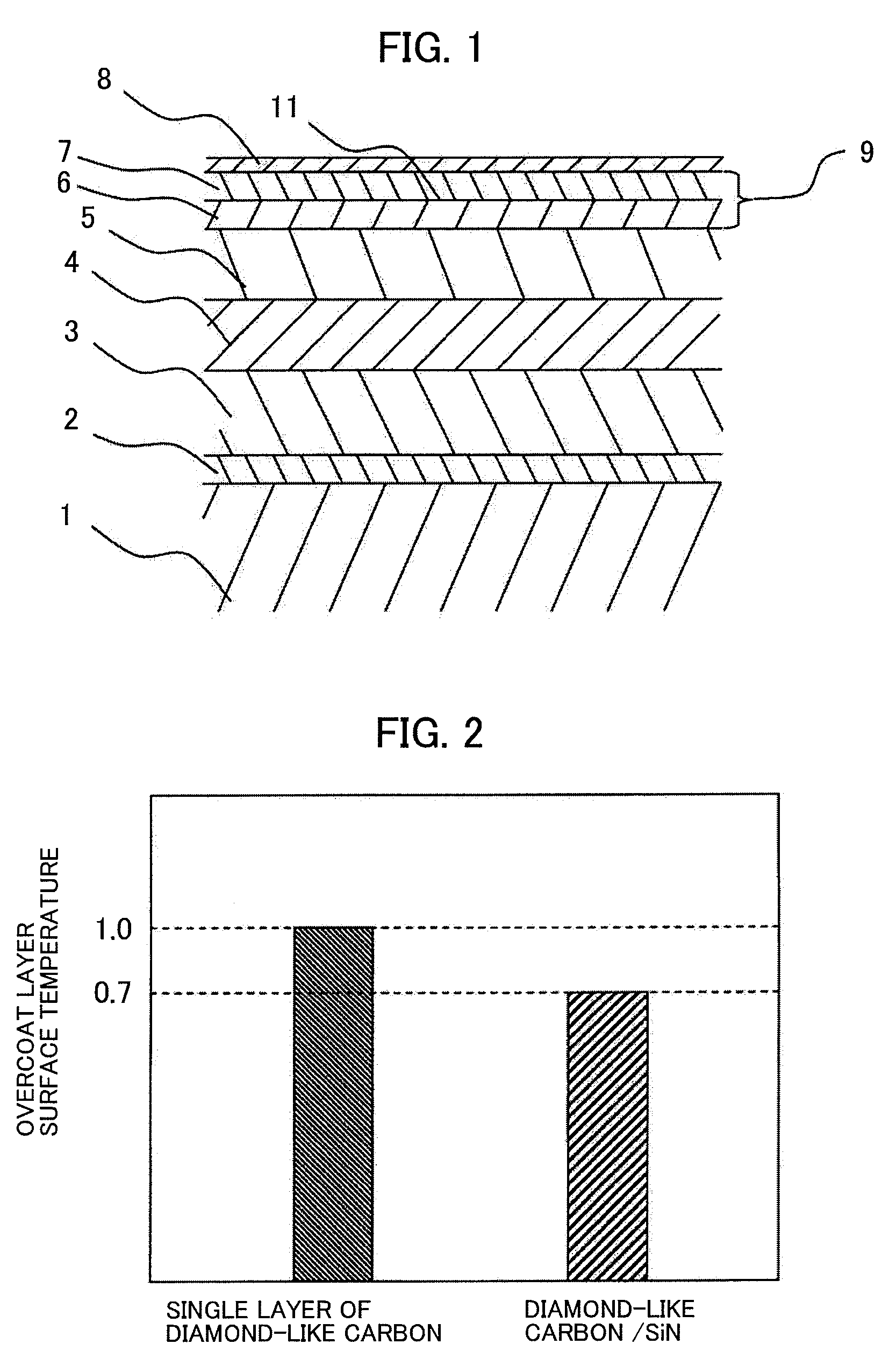
[0024]FIG. 1 is a block diagram for showing the cross-section of the magnetic disk, enlargedly, according to a first embodiment of the present invention. With the structures of the magnetic disk according to the present embodiment, on a substrate 1 are laminated an underlayer 2, a soft magnetic underlayer 3, an intermediate layer 4, a recording layer 5 and an overcoat layer 9, sequentially, with using a film forming method, such as, a spattering and / or a chemical vapor deposition method, etc., for example, and a lubricant 8 is painted on the overcoat layer 9. The overcoat layer 9 has laminated structures made up with a first overcoat film 6 and a second overcoat film 7. For the first overcoat film 6 and the second overcoat film 7, preferably, may be applied materials, such as, SiO2, SiN or a diamond-like carbon, etc., for example, having less optical absorption of the near field light when heating.
[0025]As an example, as the first overcoat film 6 is formed a film of SiN with thickne...
embodiment 2
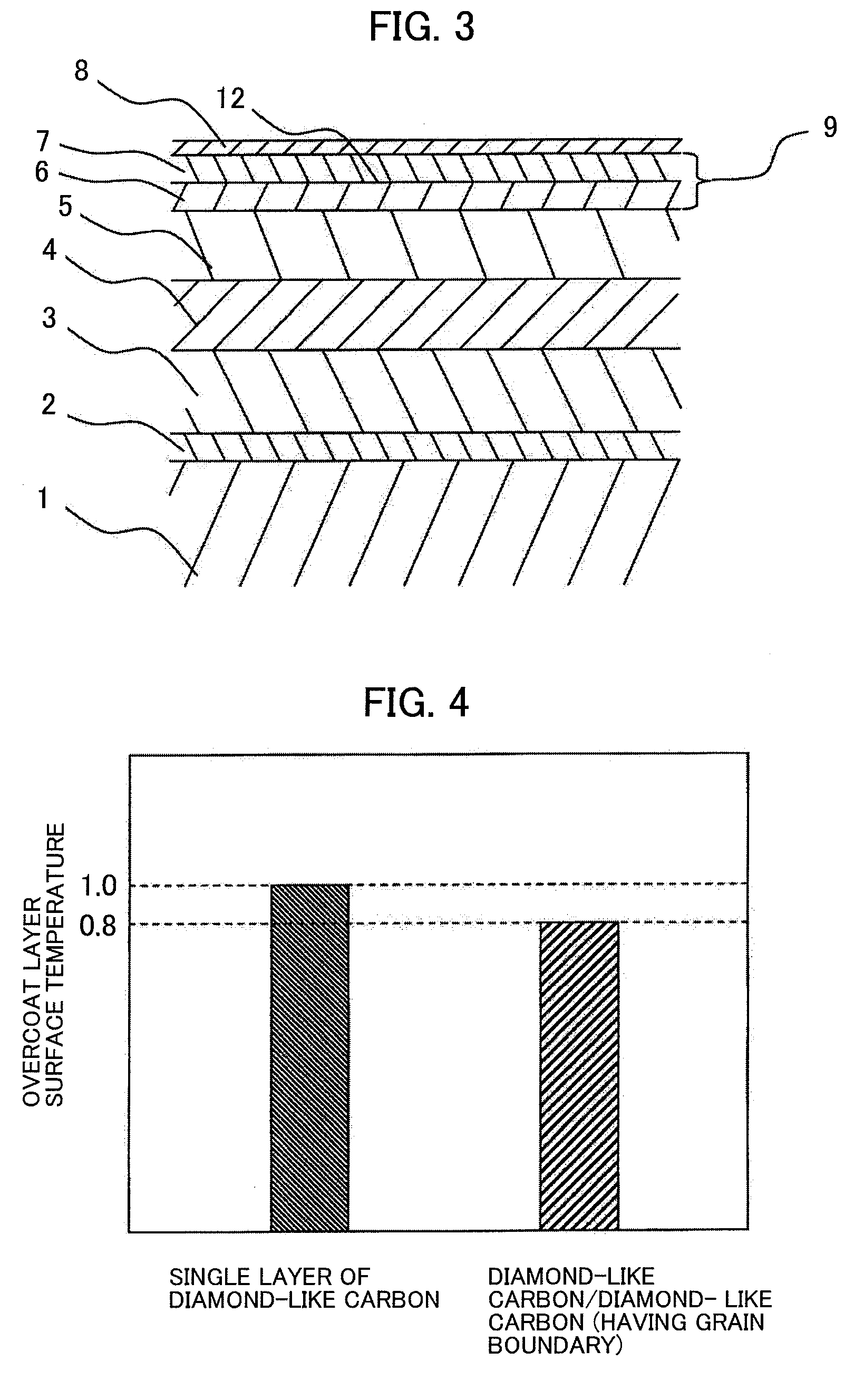
[0029]FIG. 3 is a block diagram for enlargedly showing the cross-section of the magnetic disk, according to a second embodiment of the present invention. The magnetic disk of the present embodiment is in the structures of, as is shown in FIG. 3, laminating the underlayer 2, the soft magnetic underlayer 3, the intermediate layer 4, the recording layer 5 and the overcoat layer 9, sequentially, with using a film forming method, such as, a spattering and / or a chemical vapor deposition method, etc., for example, and the lubricant 8 is painted on the overcoat layer 9. The overcoat layer 9 has the structure of laminating the first overcoat layer 6 and the second overcoat layer. According to the present embodiment, a same material is applied to the first overcoat layer 6 and the second overcoat layer 7, but forming a film with changing the condition thereof, and thereby providing a grain boundary surface 12 having a large heat resistance, within the overcoat layer 9, in parallel with the su...
embodiment 3
[0033]FIG. 5 is a block diagram for showing the cross-section of the magnetic disk, enlargedly, according to a third embodiment of the present invention. With the structures of the magnetic disk according to the present embodiment, on the substrate 1 are laminated the underlayer 2, the soft magnetic underlayer 3, the intermediate layer 4, the recording layer 5 and the overcoat layer 9, sequentially, with using a film forming method, such as, the spattering and / or the chemical vapor deposition method, etc., for example, and the lubricant 8 is painted on the overcoat layer 9. The overcoat layer 9 has three (3)-layers structure, including the first overcoat film 6, the second overcoat film 7, and a third overcoat film 10.
[0034]For the first overcoat film 6, the second overcoat film 7 and the third overcoat film 10, to be used as the overcoat layer, preferably, may be applied the materials, such as, SiO2, SiN or a diamond-like carbon, etc., for example, having less optical absorption of...
PUM
| Property | Measurement | Unit |
|---|---|---|
| temperature | aaaaa | aaaaa |
| thickness | aaaaa | aaaaa |
| thickness | aaaaa | aaaaa |
Abstract
Description
Claims
Application Information
 - R&D
- Intellectual Property
- Life Sciences
- Materials
- Tech Scout
- Unparalleled Data Quality
- Higher Quality Content
- 60% Fewer Hallucinations
Browse by: Latest US Patents, China's latest patents, Technical Efficacy Thesaurus, Application Domain, Technology Topic, Popular Technical Reports.
© 2025 PatSnap. All rights reserved.Legal|Privacy policy|Modern Slavery Act Transparency Statement|Sitemap|About US| Contact US: help@patsnap.com


