
Image processing system, image processing method, and computer program

a technology of image processing and image, applied in the field of image processing system, image processing method, and computer program, can solve the problems of misdetection of light reflection as an object, misdetection of shadow as an object, misdetection of reflected light as an object, etc., to reduce the misreporting of alerts and accurately detect moving bodies.

Active Publication Date: 2009-12-24
SONY CORP
View PDF3 Cites 26 Cited by
  • Summary
  • Abstract
  • Description
  • Claims
  • Application Information

AI Technical Summary

Benefits of technology

The present invention provides an image processing system, method, and computer program that can accurately detect a moving body object in an image, even when a mask area is set. This helps to reduce misreporting of alerts and ensures accurate monitoring of intruders or other moving objects.

Problems solved by technology

Therefore, such light reflection is misdetected as an object via the monitoring camera in the moving body detection algorithm.
Therefore, such a shadow is misdetected as an object via the monitoring camera in the moving body detection algorithm.
Therefore, the reflected light is misdetected as an object via the monitoring camera in the moving body detection algorithm.

Method used


Image

  • Image processing system, image processing method, and computer program
  • Image processing system, image processing method, and computer program
  • Image processing system, image processing method, and computer program

Examples


Embodiment Construction

[0033]An embodiment of the present invention is explained in detail below with reference to the accompanying drawings.

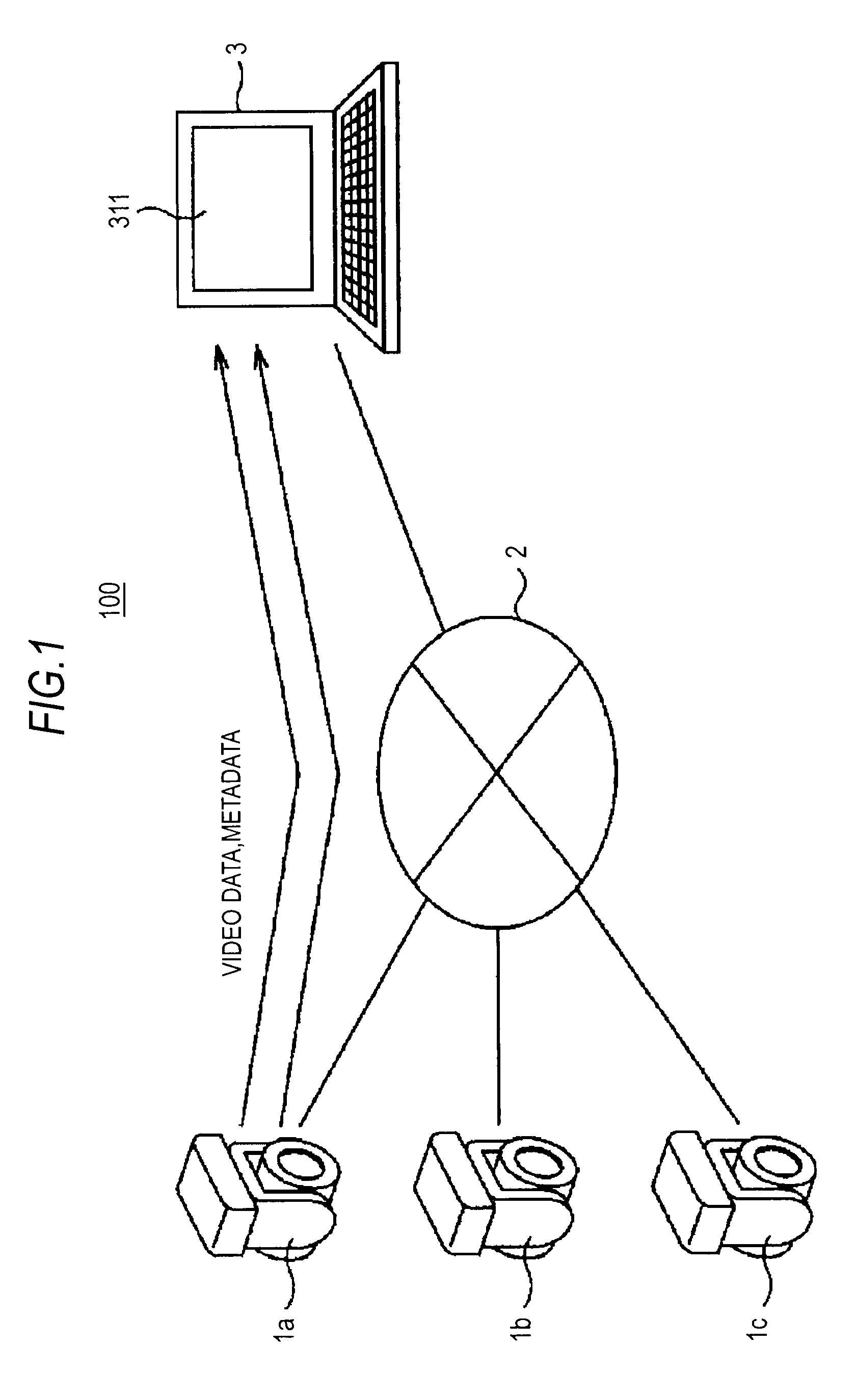
[0034]FIG. 1 is a diagram of a configuration example of a monitoring system according to an embodiment of the present invention. In a monitoring system 100 shown in FIG. 1, a client terminal 3 acquires, via a network, data output from one or plural monitoring cameras.

[0035]In the monitoring system 100, three monitoring cameras 1a, 1b, and 1c are connected to the client terminal 3 via a network 2. The client terminal 3 may be any information processing apparatus including a display unit such as a personal computer as shown in FIG. 1.

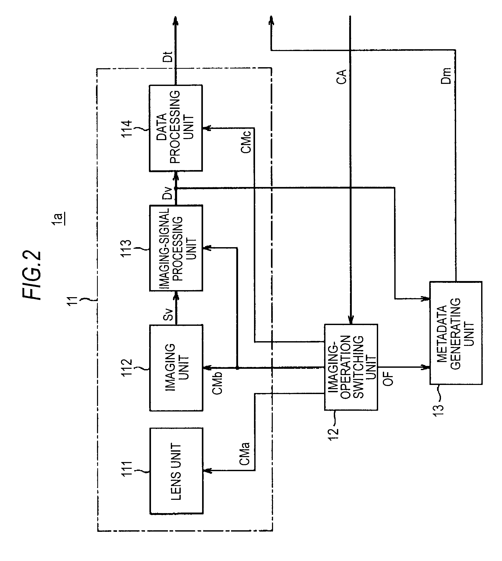
[0036]The monitoring cameras 1a, 1b, and 1c respectively photograph, in frame units, a monitoring target moving body in monitoring areas to generate image data and generate metadata from the image data of each frame. In this embodiment, examples of a monitoring target object include various moving bodies such as a person, a car, a bicycle,...


PUM


Abstract

An image processing system includes: an object detecting unit that detects a moving body object from image data of an image of a predetermined area; an object-occurrence-position detecting unit that detects an occurrence position of the object detected by the object detecting unit; and a valid-object determining unit that determines that the object detected by the object detecting unit is a valid object when the object is present in a mask area set as a non-detection target in the image of the predetermined area and the occurrence position of the object in the mask area detected by the object-occurrence-position detecting unit is outside the mask area.

Description

BACKGROUND OF THE INVENTION[0001]1. Field of the Invention[0002]The present invention relates to an image processing system, an image processing method, and a computer program for analyzing an input image and outputting a monitoring result.[0003]2. Description of the Related Art[0004]There is an image processing system that analyzes an image obtained by photographing a predetermined area with a monitoring camera and detects a moving body such as a person or a car to thereby perform monitoring (hereinafter referred to as monitoring system).[0005]FIG. 9 is a diagram of a state of moving body detection in such a monitoring system. A monitoring camera (not shown) photographs, from the front, a person 51 as a moving body and a sign 52 as a background object located behind the person 51. The person 51 is captured in a moving body detection frame 53 as an object to be monitored. In such moving body detection processing, it is possible to apply an algorithm for calculating temporal changes ...

Claims


Application Information

Patent Timeline
Patent Type & Authority Applications(United States)
IPC IPC(8): G06K9/00
CPCG06T7/20G08B13/19671G06T2207/30232G06T2207/30196
Inventor TAKEUCHI, HIDETO
Owner SONY CORP
Learn More