System for the Remote Control of Setting Up a Supporting Head for Optical and/or Photo-Cinematographic Equipment

a technology of optical and/or photocinematographic equipment and remote control, which is applied in the direction of optics, instruments, camera body details, etc., can solve the problems of inability of the operator to set up/lock the supporting head and take the photograph or photo-cinematographic shot at the same time, and restrict the effect of the restriction

Inactive Publication Date: 2009-12-24
LINO MANFROTTO & CO SPA
View PDF4 Cites 35 Cited by
  • Summary
  • Abstract
  • Description
  • Claims
  • Application Information

AI Technical Summary

Benefits of technology

[0009]The problem that lies at the heart of the present invention is to provide a system for the remote control of a device to set up an adjustable head for optical and/or photo-cinematographic equipment which is structurally and operationally designed so as to o...

Problems solved by technology

This intervention, however, means that it is impossible for the operator to set up/lock the supporting head and at the same time take the photograph or photo-cinematographic shot, because the h...

Method used


Image

  • System for the Remote Control of Setting Up a Supporting Head for Optical and/or Photo-Cinematographic Equipment
  • System for the Remote Control of Setting Up a Supporting Head for Optical and/or Photo-Cinematographic Equipment
  • System for the Remote Control of Setting Up a Supporting Head for Optical and/or Photo-Cinematographic Equipment

Examples


second embodiment

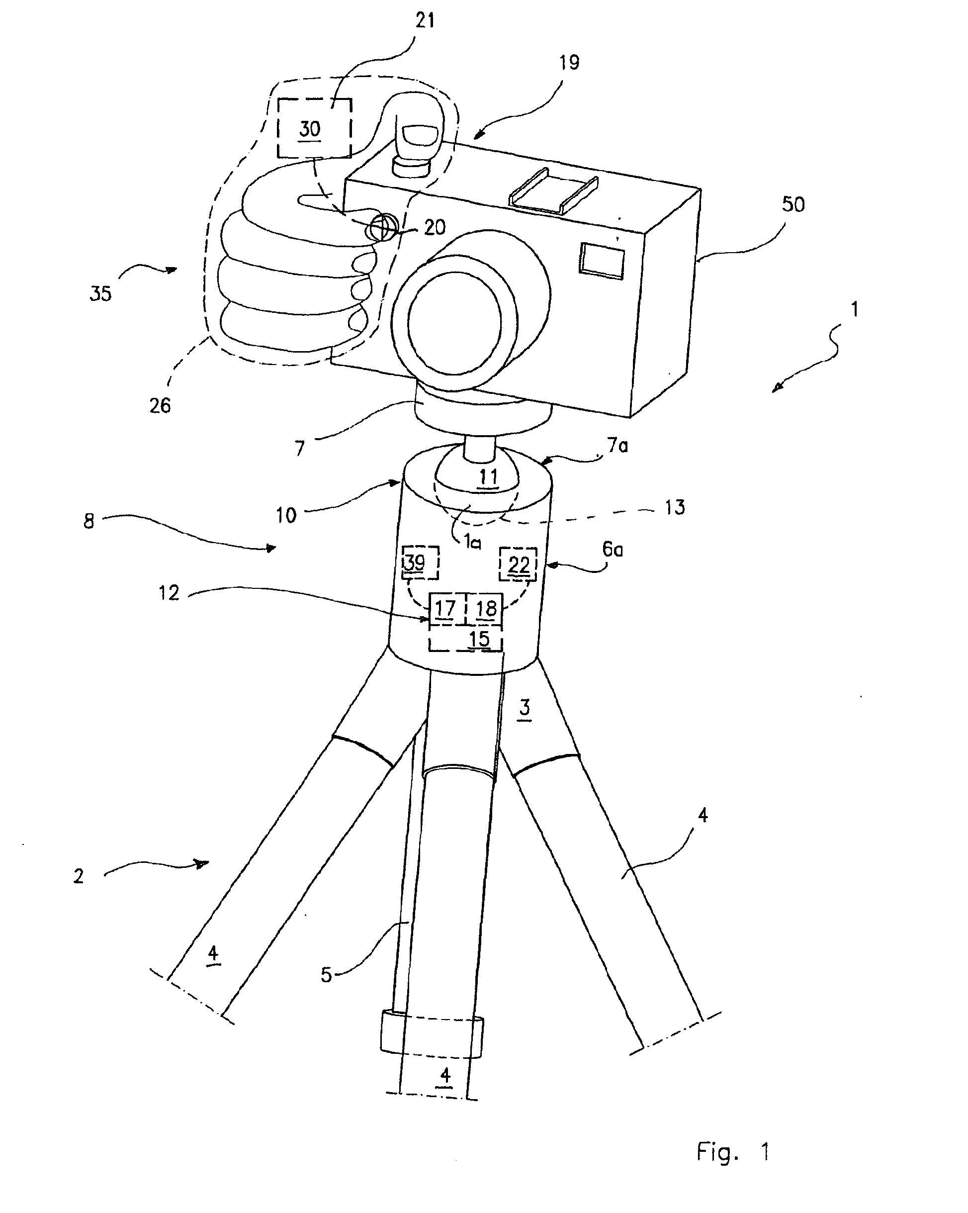
[0049]In this invention, shown in FIG. 2, the system 1 comprises the remote control means 19 including the pushbutton control 20 arranged in a removable manner on the equipment 50. In particular, the pushbutton control 20 is connected to the equipment 50 by an adhesive means or similar anchoring means. Similarly, the transmitter 21 (shown in dotted lines in FIG. 2) is arranged on the equipment by gripping means, such as a slide 40 that can be inserted in the flash-holder guide 41. Alternatively, the transmitter 21 can be mounted on the plate 7 beneath the equipment 50 (see the dotted outline in FIG. 2).

[0050]In another preferred embodiment of the invention in which a connection is provided via an electrical wire (shown by the dotted line 61 in FIG. 2) between the pushbutton 20 and the receiver 22, arranged near the joint 10′, the presence of the transmitter 21 is not required.

[0051]In this preferred embodiment too, shown in FIG. 2, the servomechanism 12, arranged on the joint 10, is...

fourth embodiment

[0054]In this invention, shown in FIG. 4, the system 1 comprises a joint 10″ that is especially for setting up video cameras 50.

[0055]The remote control means 19 including the pushbutton 20 are located on a handle 27 that extends from the body la of the head 8. The handle 27 also comprises the transmitter 21 connected to the receiver 22 (neither of which are shown in FIG. 4) which is in turn connected to the servomechanism 12, built into the articulated joint 10″ as in the preceding embodiments. Alternatively, an electrical wire 28 is provided which connects the pushbutton control 20 to the servomechanism 12. On the handle 27, near the said pushbutton control 20, there may be additional pushbuttons 55 relating to the control of the video camera 50. Consequently, using the same hand, it is possible to manoeuvre the video camera via its control buttons 55 and to set up and / or lock / unlock it by means of pushbutton 20.

[0056]Although in the above-described embodiments a pushbutton contro...


PUM


Abstract

This invention describes a system for the remote control of setting up an adjustable head for optical and/or photo-cinematographic equipment comprising an adjustable head for mounting by adjustable setting-up of optical and/or photo-cinematographic equipment, at least one servomechanism for locking and/or unlocking and/or setting up a movable part of the head in relation to a fixed part thereof, as well as remote control means of said servomechanism for setting up the head comprising at least one pushbutton control, remote in relation to the servomechanism, that can be operated by the user while he is holding said equipment.

Description

TECHNICAL FIELD [0001]This invention relates to a system for the remote control of setting up an adjustable supporting head for optical and / or photo-cinematographic equipment according to the pre-characterising clause of main claim 1.BACKGROUND ART [0002]Supporting heads that can be adjusted in a plurality of directions are known to be used for mounting and adjusting in the desired manner (henceforth “setting up”) a still camera, video camera or other optical and / or photo-cinematographic equipment on a support therefor such as a tripod, stand or similar supports known in the technical sector in question.[0003]In known solutions, these supporting heads usually afford one or more set-up possibilities (generally two for video cameras, three for still cameras) about the same number of axes, and the possible connections between the head and support capable of achieving these adjustments are of different types, such as one or more articulated joints, preferably of a ball or cylindrical ty...

Claims


Application Information

Patent Timeline
IPC IPC(8): G03B17/00
CPCF16M11/14G03B17/56F16M11/18G03B17/561G03B17/563F16M2200/022F16M2200/024
Inventor DAVID, LAURENT
Owner LINO MANFROTTO & CO SPA
Why Eureka
Try Eureka