

Optical space transfer apparatus using image sensor
a technology of image sensor and optical space transfer, applied in the direction of line-of-sight transmission, electromagnetic transmission, transmission, etc., to achieve the effect of reducing the required degree of precision of optical axis adjustment, high speed communication, and increasing the signal reading speed of an image sensor
- Summary
- Abstract
- Description
- Claims
- Application Information
AI Technical Summary
Benefits of technology
Problems solved by technology
Method used
Image

Examples
first embodiment
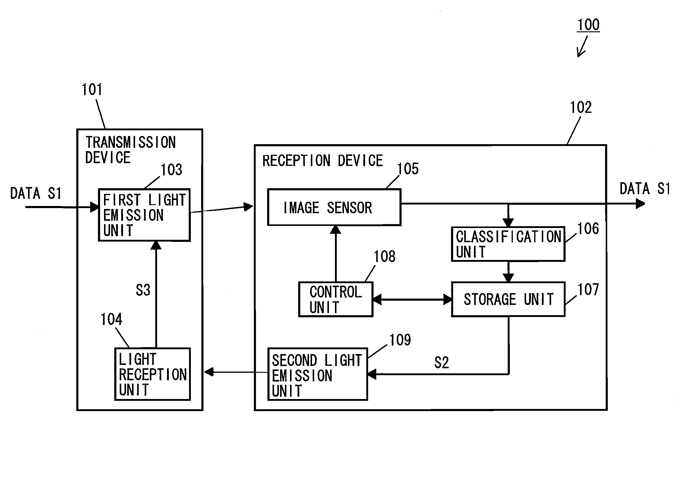
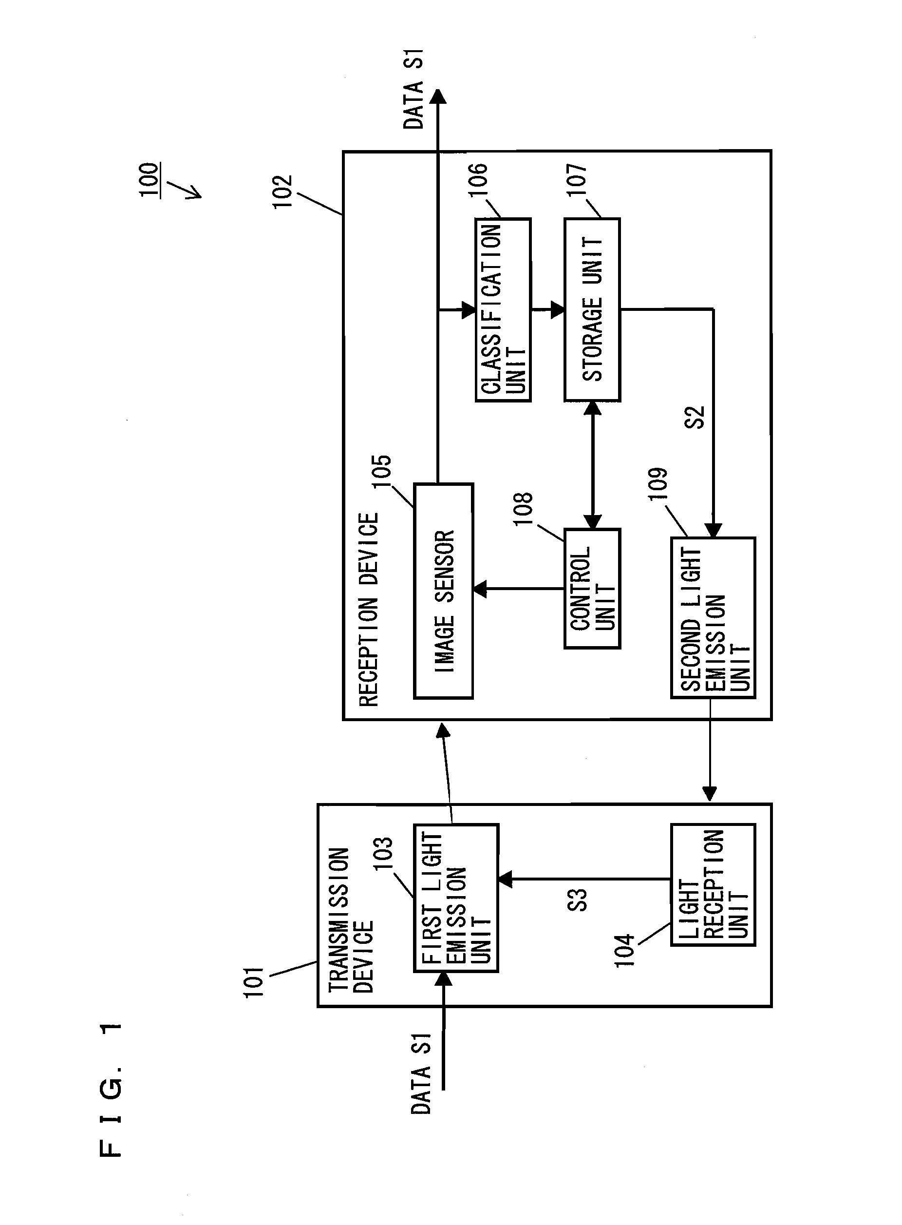
[0067]FIG. 1 shows an example of a structure of an optical space transfer apparatus 100 according to a first embodiment of the present invention. As shown in FIG. 1, the optical space transfer apparatus 100 includes a transmission device 101 and a reception device 102. The transmission device 101 includes a first light emission unit 103 and a light reception unit 104. The reception device 102 includes an X-Y address system image sensor (hereinafter, referred to simply as an “image sensor”) 105, a classification unit 106, a storage unit 107, a control unit 108, and a second light emission unit 109.
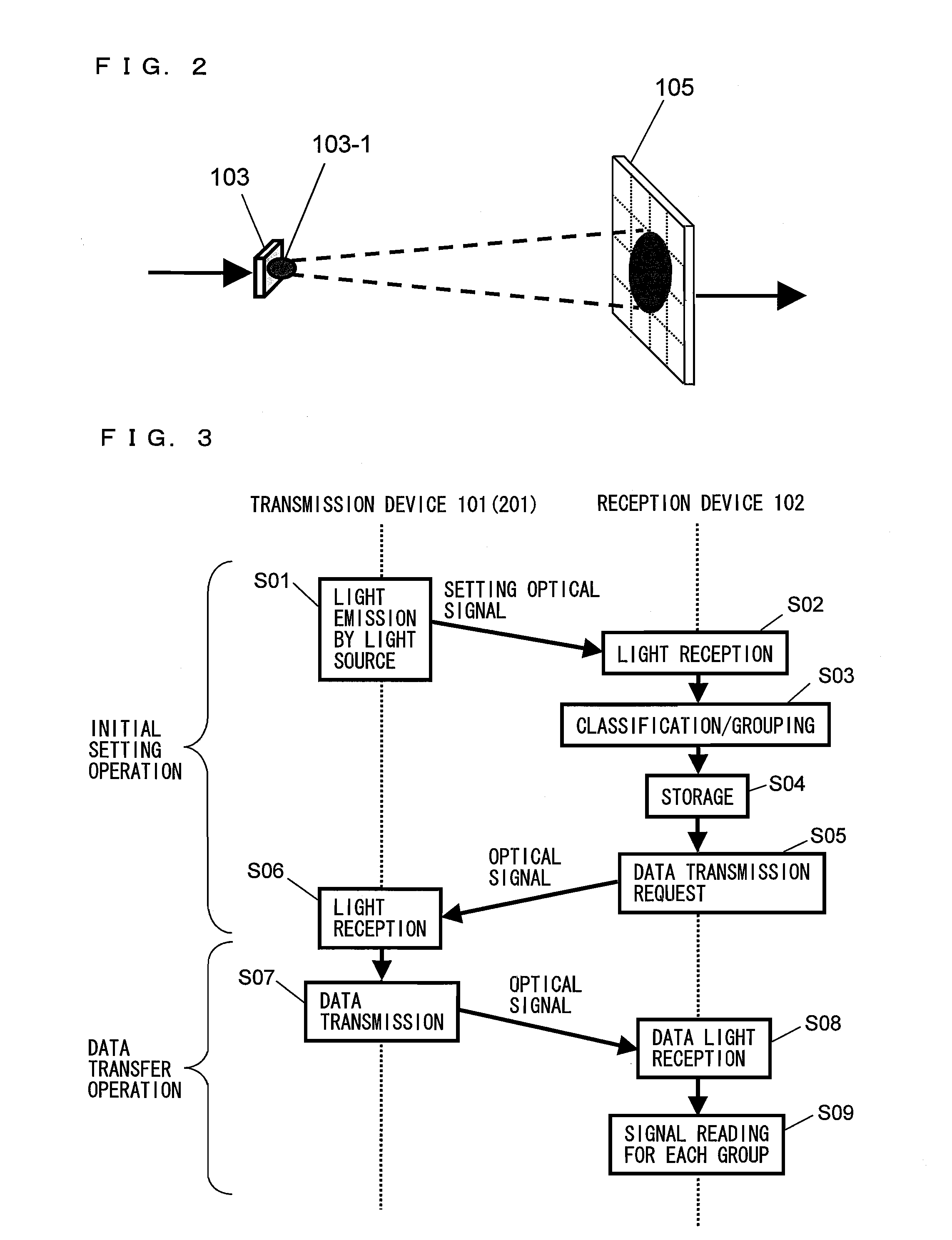
[0068]FIG. 2 specifically shows the first light emission unit 103 and the image sensor 105. As shown in FIG. 2, the first light emission unit 103 includes one light source 103-1. The image sensor 105 has a pixel region including a plurality of pixels. Hereinafter, the image sensor 105 will be described as including 16 pixels as an example.
[0069]FIG. 3 illustrates an operation of the optical...
second embodiment
[0090]In the first embodiment, an optical signal is transferred along one optical axis. In a second embodiment, an optical signal is transferred along a plurality of optical axes. An operation period of each pixel of the image sensor includes a signal accumulation period for accumulating signals and a signal reading period of reading the accumulated signals. Namely, the pixels cannot accumulate signals during the signal reading period. In the case where an optical signal is transferred along a plurality of optical axes, while signals of a group of pixels are read collectively (signal reading period), signals can be accumulated in another group of pixels. Namely, according to the second embodiment, by transferring an optical signal along a plurality of optical axes for data communication, a decrease of the transfer speed, which is otherwise caused by the signal reading period, can be avoided. In the meantime, in the second embodiment, in order to perform data communication, it is nec...
third embodiment
[0110]In the first and second embodiments, there is a premise that the positional relationship between the transmission device and the reception device is not changed. In a third embodiment, a structure, which is adaptable in the optical space transfer apparatus according to the first or second embodiment and is capable of realizing data communication accurately even when the positional relationship between the transmission device and the reception device is changed and the optical axis is shifted, will be described. In the following description, the optical space transfer apparatus 200 according to the second embodiment will be used as an example.
[0111]In the third embodiment, the transmission device 201 further includes a pilot light source, which is a light source for optical axis correction. The pilot light source may be included in the first light emission unit 203. The pilot light source irradiates the pixel region of the image sensor 105 with a pilot optical signal, which is ...
PUM
 Abstract
Description
Claims
Application Information