Image formation apparatus and image formation method

a technology of image formation apparatus and image, which is applied in the direction of electrographic process apparatus, ohmic resistance heating, instruments, etc., can solve the problems of deterioration of rotating bodies and peripheral parts, excessive rise of rotating bodes, and poor usability of methods, so as to reduce the amount of overshoot, reduce the length of time that heat is continuously applied, and reduce the negative influence of temperature elevation

Active Publication Date: 2009-12-24
KONICA MINOLTA BUSINESS TECH INC
View PDF5 Cites 0 Cited by
  • Summary
  • Abstract
  • Description
  • Claims
  • Application Information

AI Technical Summary

Benefits of technology

[0016]According to this structure, prior to performing temperature control to reach the standby state, when the fixing temperature is the highest temperature that can be set, the rotating bodies in the fixing device are caused to rotate, and the temperature is regulated to be a lower temperature than the fixing temperature at that time. Once the temperature of the rotating bodies has been lowered, the rotating bodies are stopped. Therefore, this structure enables alleviating the negative influence of a temperature elevation in the rotating bodies due to stopping the rotation thereof. In addition, when the fixing temperature is the lowest temperature that can be set, the rotating bodies in the fixing device are caused to rotate, and the temperature is regulated to be a higher temperature than the fixing temperature at that time. Once the temperature of the rotating bodies has been raised, a transition is made to the standby state. Therefore, in a case in which a temperature regulation setting in the standby state is set to a high temperature, this structure enables reducing the length of time that heat is continuously applied to the rotating bodies, reducing the amount of overshoot, and alleviating the negative influence of overshoot.
[0017]Accordingly, the temperature of the rotating bodies can be appropriately controlled so that the temperature neither becomes too high nor reaches, as in the conventional technology, an unnecessarily low temperature.

Problems solved by technology

However, when the time to form the image arrives, it is necessary to wait for the temperature to rise to a sufficient temperature for fixing.
Since this prolongs the time waiting for printing to start, this method has remarkably poor usability, and so is not preferable.
In a case that the temperature at the time that fixing ends is near an upper end, a problem arises that if rotation of the rotating bodies is stopped soon after the fixing ends, the temperature of the rotating bodes rises too high, leading to deterioration of the rotating bodies and peripheral parts.
As can be seen in an example of using a halogen heater as the heater, since this type of heater has an attribute such that the temperature thereof rises quickly when turned ON and falls comparatively quickly when turned OFF, lowering the temperature of the roller pair is nearly impossible even when the temperature of the heater is detected and control is performed.
Therefore, achieving the described advantageous effect with use of this type of structure is considered impossible.
However, when the fixing temperature is a low temperature, the temperature falls too low.
Therefore, similarly to the case of document 1, if the fixing temperature is a low temperature, the temperature falls too low, and if a printing instruction is received at such a time, the waiting time until printing starts is prolonged and fixing faults are likely to occur.
In addition, another problem arises, namely that fixing is forcibly stopped when an abnormally low temperature error is erroneously detected.
However, in a case that a transition from a low temperature to the standby temperature is always made when the rotation of the rotating bodies have stopped, such as in document 1 and document 2, if the temperature setting in standby is a high temperature, there tends to be a large overshoot due to applying heat to the rotating bodies for a long period of time.
Accordingly, a new problem arises that the temperature of the rotating bodies becomes too high, leading to deterioration of the rotating bodies and the peripheral parts.

Method used


Image

  • Image formation apparatus and image formation method
  • Image formation apparatus and image formation method
  • Image formation apparatus and image formation method

Examples


embodiment 1

[0032]Overview

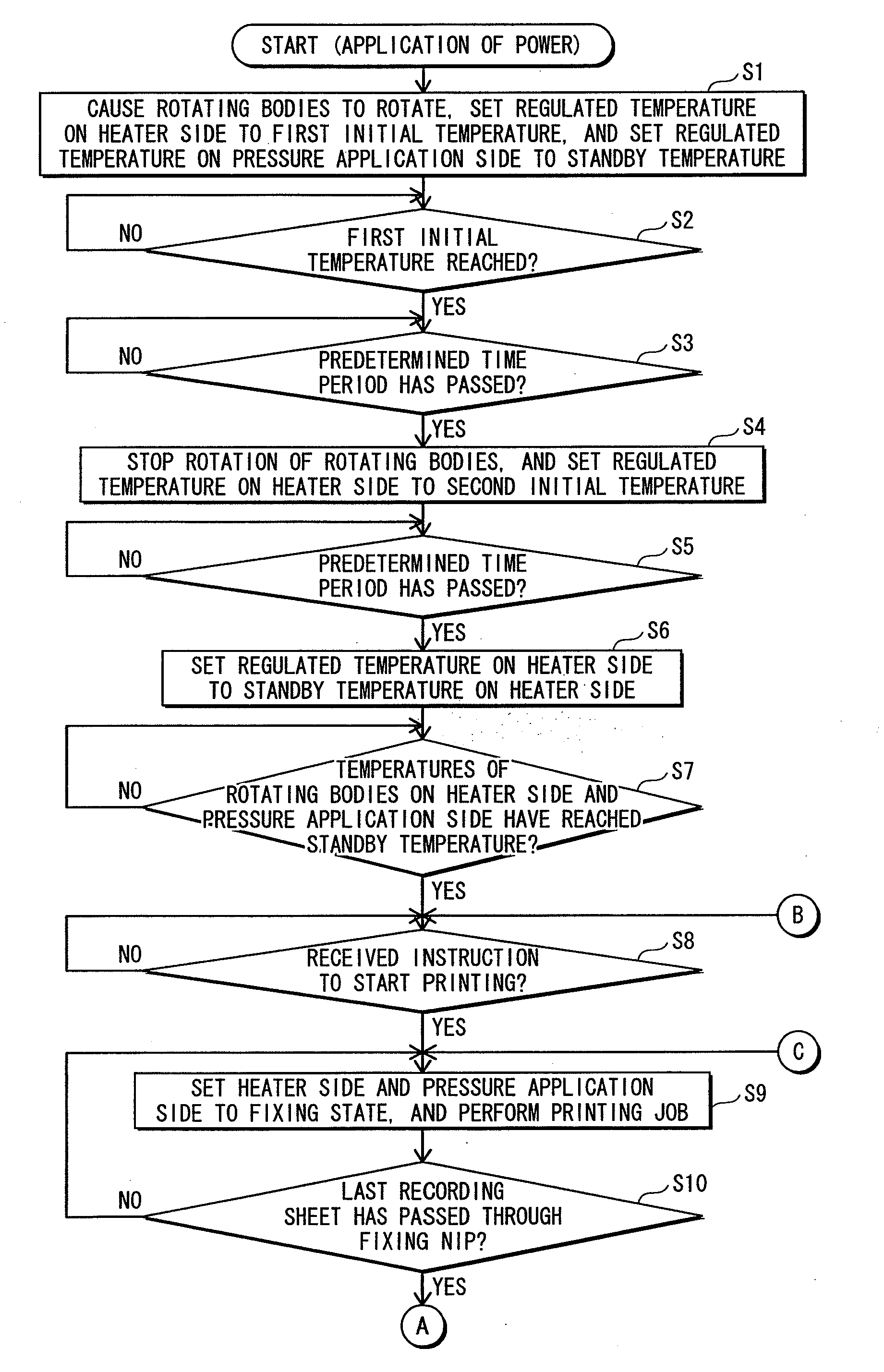
[0033]Embodiment 1 is an image formation apparatus including a fixing device. In a case of, in a standby state, causing rotating bodies in the fixing device to stop and regulating a temperature thereof so that a predetermined standby temperature is reached, upon judging that fixing has finished, the image formation apparatus of embodiment 1 lowers the regulated temperature when a fixing temperature is comparatively high, and raises the regulated temperature when the fixing temperature is comparatively low, without causing the rotating bodies to stop. The image formation apparatus thereafter causes the rotating bodies to stop, and after a temperature elevation due to stopping the rotation of the rotating bodies has subsided, controls the temperature of the rotating bodies appropriately so that the temperature of the rotating bodies does not become too high and does not become unnecessarily low by raising the regulated temperature to the standby temperature.

[0034]Structu...


PUM


Abstract

A standby state is a state in which a pair of rotating bodies stops rotating, and temperature control is performed so that at least one of the rotating bodies reaches a standby temperature. A fixing state is a state in which the rotating bodies are rotating and temperature control is performed so that at least one of the rotating bodies reaches a fixing temperature that changes in accordance with a setting. An image formation apparatus includes a judgment part for judging whether to transition from the fixing state to the standby state, and a fixing controller for, upon a judgment by the judgment part to transition to the standby state, prior to performing temperature control to reach the standby temperature, causing the pair of rotating bodies to rotate, and performing temperature control so that the temperature of at least one of the rotating bodies reaches a predetermined transition temperature range including temperatures higher than a lowest temperature that can be set as the fixing temperature, and lower than a highest temperature that can be set as the fixing temperature.

Description

[0001]This application is based on application No. 2008-159998 filed in Japan, the content of which is hereby incorporated by reference.BACKGROUND OF THE INVENTION[0002]1. Field of the Invention[0003]The present invention relates to an image formation apparatus including a fixing device, and in particular to technology for appropriately controlling a temperature of rotating bodies such as fixing rollers and pressure application rollers in the fixing device, in a case of, in a standby state, stopping the rotating bodies and regulating the temperature thereof to reach a predetermined standby temperature.[0004]2. Description of Related Art[0005]In general, in image formation apparatuses including fixing devices that use a heat roller fixing method, stopping rotation of rotating bodies in the fixing device when in a standby state enables suppressing deterioration of the rotating bodies and peripheral parts, reducing noise, and realizing an energy-conserving effect to some degree.[0006]H...

Claims


Application Information

Patent Timeline
Patent Type & Authority Applications(United States)
IPC IPC(8): G03G15/20
CPCG03G15/2039G03G2215/2019
Inventor OTSUKA, YUTAKA
Owner KONICA MINOLTA BUSINESS TECH INC
Why Eureka
Try Eureka