Particulate matter detection device

Active Publication Date: 2019-04-11
DENSO CORP
View PDF1 Cites 0 Cited by
  • Summary
  • Abstract
  • Description
  • Claims
  • Application Information

AI Technical Summary

Benefits of technology

[0012]In the above-described particulate matter detection device, the sensor control unit actuates the capture control unit to start electrostatic capturing of the particulate matter. Meanwhile, the heating control unit is actuated to heat the detection unit to the first temperature, thereby acquiring the first output value corresponding to the particulate matter from which the SOF has been volatilized. Further, the heating control unit is actuated to heat the detection unit to the second temperature, thereby acquiring the second output value corresponding to the particulate matter right before the soot is burnt. The output changing ratio as the ratio between the first output value and the second output value correlates with the average particle diameter of the captured particulate matter, and therefore, the average particle diameter can be estimated from the output changing ratio.
[0013]The output changing ratio calculated by the output changing ratio calculation unit exhibits temperature dependency. Thus, as in one aspect as described above, the temperature correction section i

Problems solved by technology

It was discovered that issues of such variation in the sensor output also occur when the multiple PM detection un

Method used


Image

  • Particulate matter detection device
  • Particulate matter detection device
  • Particulate matter detection device

Examples


first embodiment

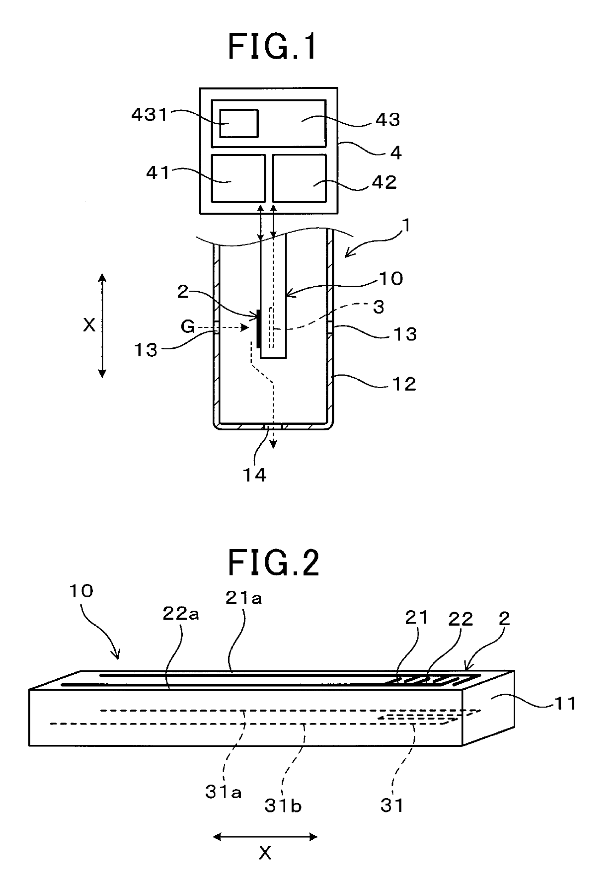
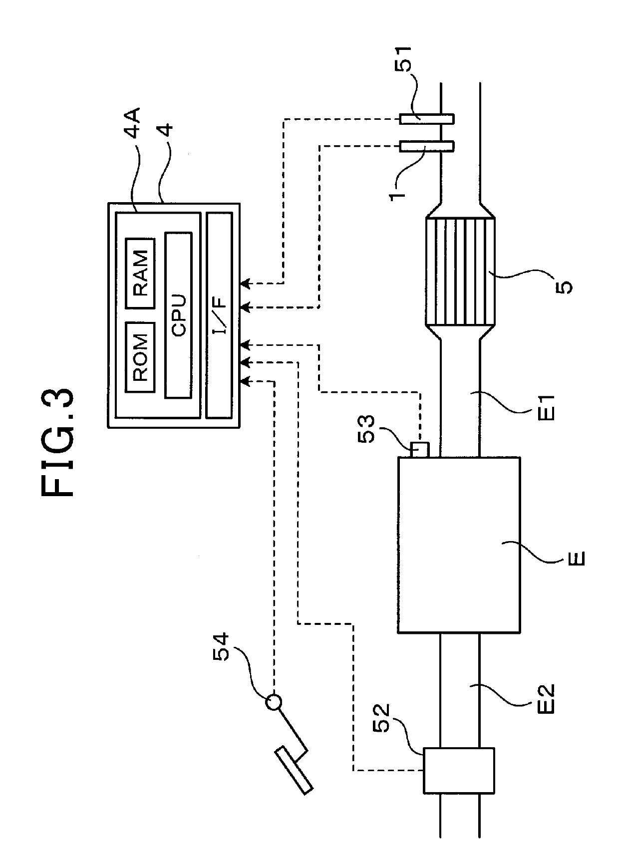
[0034]Next, an embodiment of a particulate matter detection device and a particulate matter detection method will be described with reference to the drawings. As illustrated in FIGS. 1 to 3, the particulate matter detection device includes a particulate matter detection sensor 1 as a sensor unit configured to detect a particulate matter contained in measuring gas G, and an electronic control unit 4 (hereinafter referred to as an “ECU”) as a sensor control unit configured to detect the number of particles of the particulate matter based on a detection signal from the particulate matter detection sensor 1. The ECU 4 outputs a control signal to the particulate matter detection sensor 1, thereby controlling collection and detection of the particulate matter.

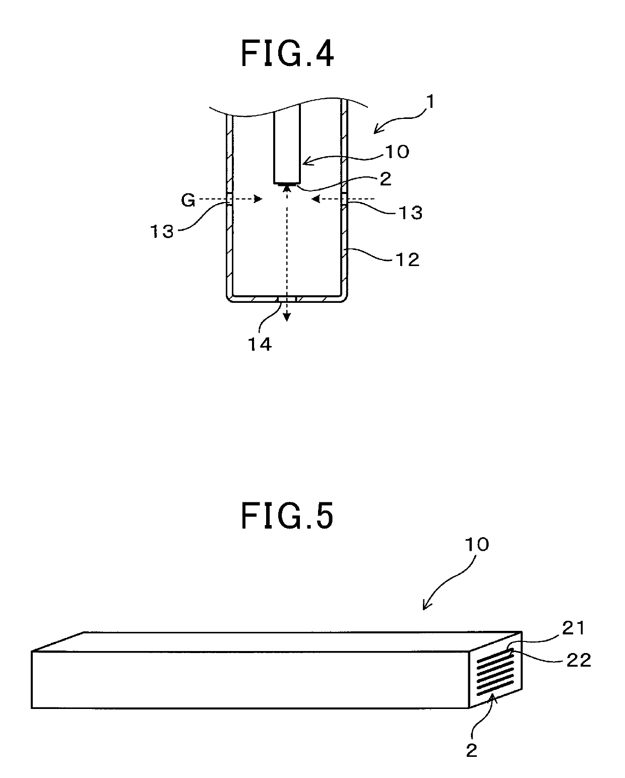
[0035]As illustrated in FIG. 1, the particulate matter detection sensor 1 includes an electrical resistance sensor element 10 and a protection cover 12 configured to cover the outer periphery of the sensor element 10. When an axial d...

second embodiment

[0069]In the first embodiment, the case where the mass M of the particulate matter is estimated based on the first output value V1 has been described, but other values than the first output value V1 can be used.

[0070]As illustrated in FIG. 12, in the present embodiment, particulate matter detection process executed by an ECU 4 as a sensor control unit is configured such that part of the procedure of the first embodiment illustrated in FIG. 6 is changed. Specifically, this process is different in that a step S111 is provided instead of step S11 of FIG. 6. Steps S1 to S10 are the same process as that of FIG. 6, and therefore, description thereof will be omitted. At step S111 of FIG. 12, the mass M of a particulate matter is estimated using a sensor output V at the time of positive determination at step S2 instead of a first output value V1 at a first temperature T1.

[0071]At step S2 of FIG. 12, it is determined whether or not the sensor output V reaches a predetermined output V0 set in...

third embodiment

[0074]In the first and second embodiments, the case where temperature correction is performed after calculation of the output changing ratio V2 / V1 has been described, but the necessity of temperature correction can be eliminated by temperature increase control. That is, in the present embodiment, a heating control unit 42 has a temperature increase control section configured to control the rate of temperature increase upon heating from a first temperature T1 to a second temperature T2. The heating control unit 42 constantly controls the rate of temperature increase until the temperature T of a sensor element 10 at least exceeds a temperature corresponding to a second output value V2. By the temperature increase control section, the temperature T of the sensor element 10 at which burning of soot begins can be stabilized, and variation in an output changing ratio V2 / V1 can be reduced.

[0075]As illustrated in FIG. 13, in the present embodiment, particulate matter detection process execu...


PUM


Abstract

A particulate matter detection device includes a sensor unit which has a detection unit provided with a pair of electrodes and a heater unit provided with a heater electrode and which is configured to output a signal corresponding to the amount of particulate matter, and a sensor control unit which detects the number of particles of the particulate matter. The sensor control unit has a capture control unit, a heating control unit to heat the detection unit to a first temperature at which a SOF is volatilizable and a second temperature at which soot is burnable, an output changing ratio calculation unit to calculate a ratio between a first output value at the first temperature and a second output value as the maximum output upon heating to the second temperature, and a particle number calculation unit to estimate the average particle diameter of the particulate matter from a value corrected based on the temperature of the sensor unit at the second output value to calculate the number of particles.

Description

CROSS-REFERENCE TO RELATED APPLICATIONTECHNICAL FIELD[0001]The present disclosure relates to a particulate matter detection device for detecting the number of particles of a particulate matter discharged from an internal combustion engine.BACKGROUND ART[0002]In response to emission constraint on a particulate substance (i.e., a particulate matter hereinafter referred to as “PM” as necessary) contained in automobile exhaust gas, it is important to enhance detection accuracy of a particulate matter detection device. The particulate matter detection device includes, for example, an electrically resistance sensor element. The particulate matter detection device is configured to form an electrostatic field by application of voltage to a detection electrode portion provided on a surface of an insulating base, thereby detecting a change in the resistance value of the detection electrode portion due to the particulate matter which is captured.[0003]The particulate matter detection device is...

Claims


Application Information

Patent Timeline
IPC IPC(8): G01N15/06
CPCG01N15/0656G01N2015/0046G01N15/0606
Inventor KOIKE, KAZUHIKOYAMAMOTO, MASAHIRO
Owner DENSO CORP
Why Eureka
Try Eureka