
Power-on reset circuit

a power-on reset and circuit technology, applied in electronic switching, pulse automatic control, pulse technique, etc., can solve the problems of circuit layout area and production cost of por circuit b>200/b>, circuit temperature is in an unstable state, circuit operation is not complete, etc., to reduce the influence of temperatur

Inactive Publication Date: 2012-04-19
UPI SEMICON CORP
View PDF3 Cites 7 Cited by
  • Summary
  • Abstract
  • Description
  • Claims
  • Application Information

AI Technical Summary

Benefits of technology

[0011]The invention is directed to a power-on reset (POR) circuit, which can reduce influence of temperature to the circuit.
[0012]The invention is directed to a POR circuit, which can reduce a layout area and production cost of the circuit.
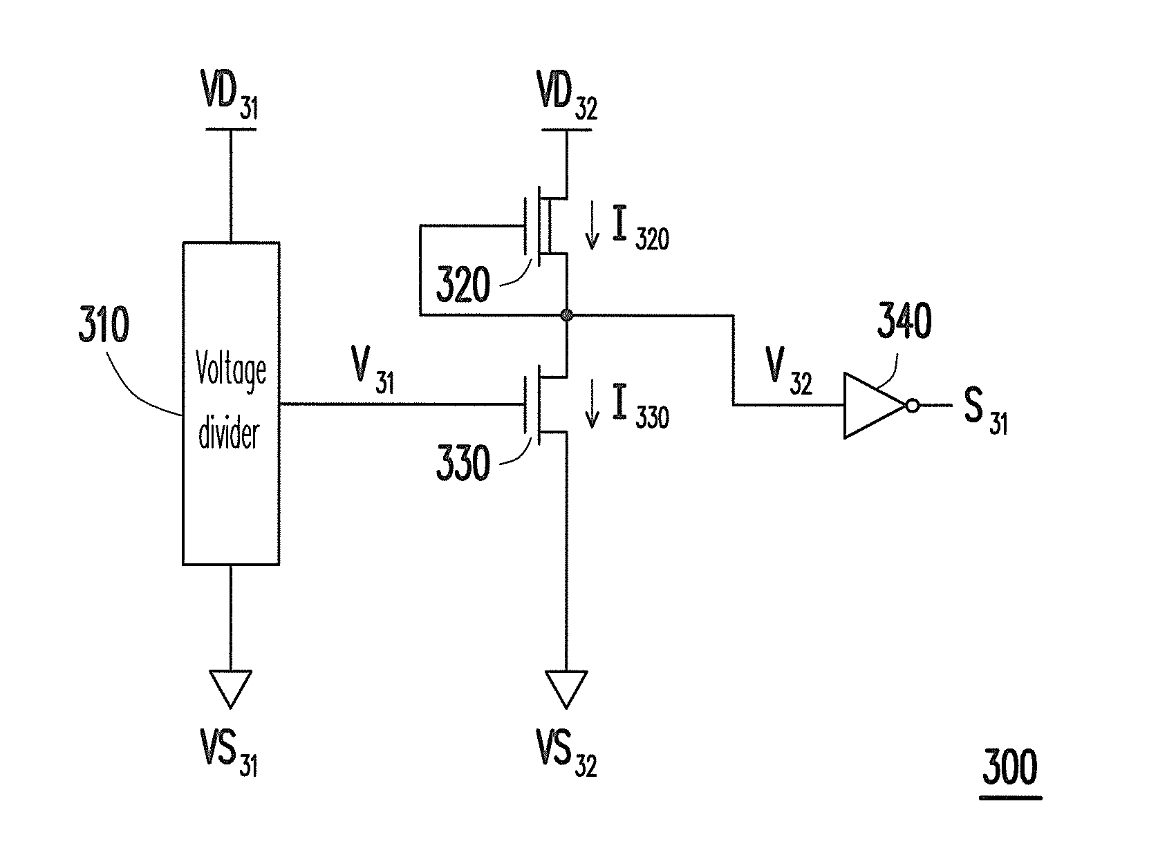
[0018]According to the above descriptions, in the invention, transistors with the same conductive channel and different types are used to generate a trip point voltage non-related to temperature. Moreover, the POR circuit of the invention compares the sensing voltage proportional to the power voltage according to the trip point voltage non-related to temperature. In this way, the POR circuit of the invention can reduce influence of temperature to the circuit, and avails reducing a layout area and production cost of the circuit.

Problems solved by technology

Generally, at an initial stage for supplying power to the electronic circuit, the electronic circuit is in an unstable state.
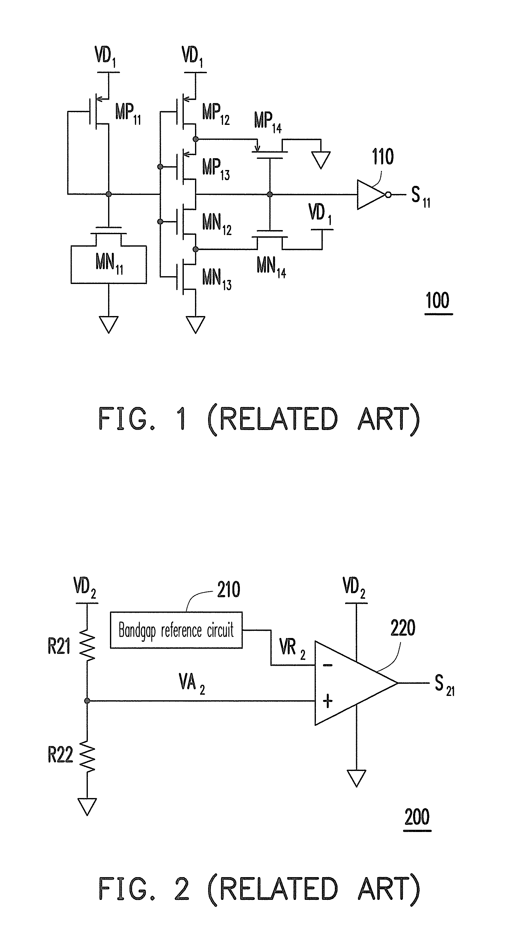
However, since a threshold voltage of a transistor is shifted due to temperature influence, the first predetermined voltage and the second predetermined voltage used for determining the power voltage VD1 are also varied along with temperature, which may cause a miss operation of the circuit.
However, circuit structures of the bandgap reference circuit 210 and the comparator 220 are relatively complicated, so that a layout area and production cost of the POR circuit 200 are correspondingly increased.
Therefore, how to effectively prevent the temperature from influencing the circuit and simultaneously optimize the layout area of the circuit is an important issue for designing a POR circuit.

Method used


Image

  • Power-on reset circuit
  • Power-on reset circuit
  • Power-on reset circuit

Examples


Embodiment Construction

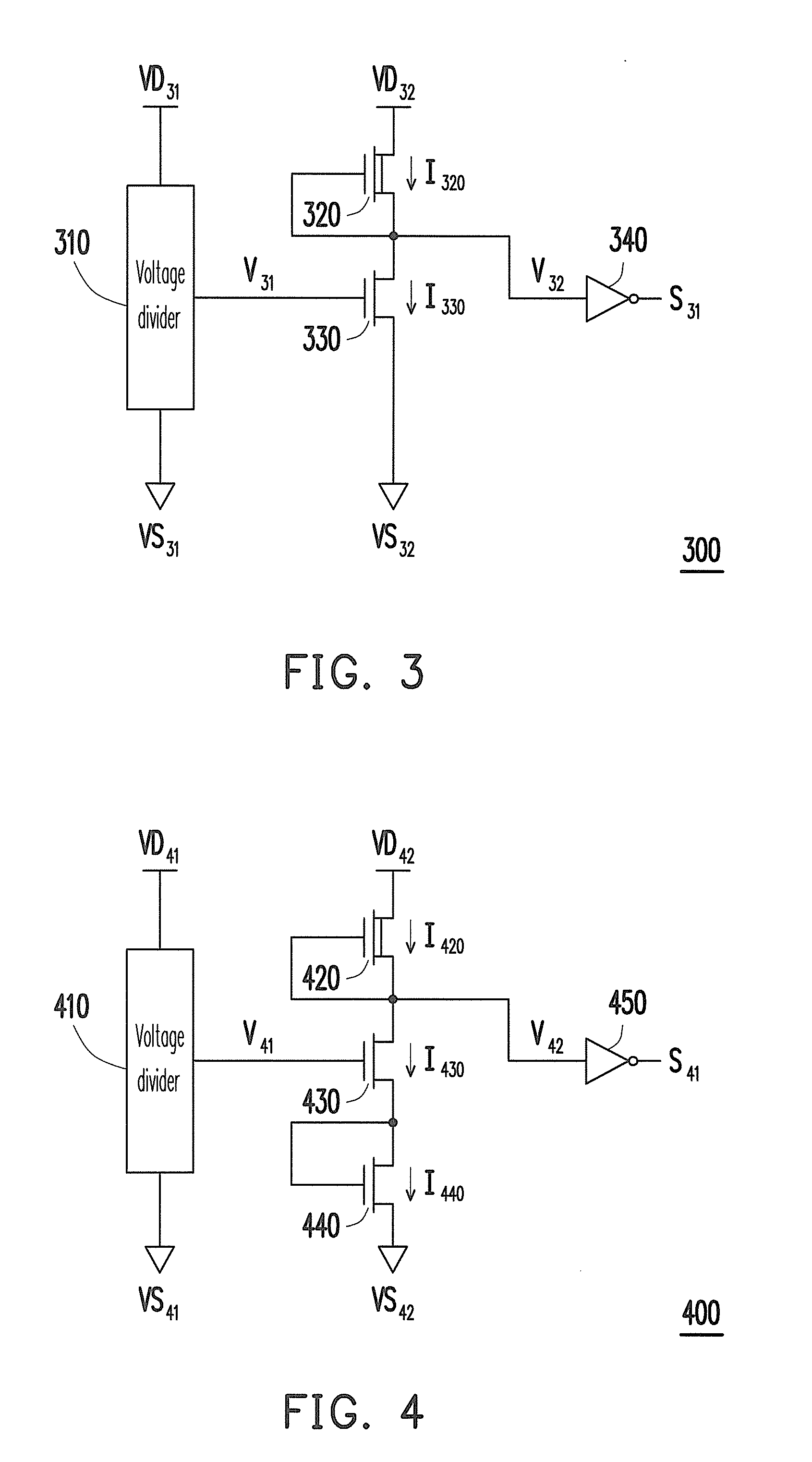
[0028]FIG. 3 is a circuit diagram of a power-on reset (POR) circuit according to an embodiment of the invention. Referring to FIG. 3, the POR circuit 300 includes a voltage divider 310, a transistor 320, a transistor 330 and an inverter 340. The transistor 320 and the transistor 330 have the same conductive channel and different types.

[0029]For example, conductive channels of the transistors include an n-channel and a p-channel, and in the present embodiment, n-channel transistors are used to implement the transistor 320 and the transistor 330. Moreover, types of the transistors include a depletion type and an enhancement type, and in the present embodiment, a depletion type transistor is used to implement the transistor 320, and an enhancement type transistor is used to implement the transistor 330. In other words, in the present embodiment, the transistor 320 is a depletion type n-channel transistor, and the transistor 330 is an enhancement type n-channel transistor. However, impl...


PUM


Abstract

A power-on reset circuit including a voltage divider, a first transistor and a second transistor is provided. The voltage divider is electrically connected between a first source voltage and a first ground voltage, and generates a sensing voltage. A drain of the first transistor is electrically connected to a second source voltage, and a gate and a source of the first transistor are connected to each other. A conductive channel of the second transistor is the same with that of the first transistor, and a type of the second transistor is different from a type of the first transistor. Furthermore, a drain of the second transistor is electrically connected to the source of the first transistor. A gate of the second transistor receives the sensing voltage. A source of the second transistor is electrically connected to a second ground voltage.

Description

CROSS-REFERENCE TO RELATED APPLICATION[0001]This application claims the priority benefit of Taiwan application serial no. 99135607, filed on Oct. 19, 2010. The entirety of the above-mentioned patent application is hereby incorporated by reference herein and made a part of this specification.BACKGROUND[0002]1. Field of the Invention[0003]The invention relates to a power-on reset circuit. Particularly, the invention relates to a power-on reset circuit capable of reducing temperature influence.[0004]2. Description of Related Art[0005]Regarding an electronic circuit, setting of an initial state thereof is very important. Generally, at an initial stage for supplying power to the electronic circuit, the electronic circuit is in an unstable state. Therefore, a power-on reset (POR) circuit is required to be designed to reset the state of the circuit during a power-on process, so as to ensure the initial state of electronic circuit to be in a predetermined state.[0006]FIG. 1 is a circuit dia...

Claims


Application Information

Patent Timeline
Patent Type & Authority Applications(United States)
IPC IPC(8): H03L7/00
CPCH03K17/102H03K17/567H03K17/223H03K17/145
Inventor CHEN, JIUN-CHIANGWANG, HAN-PANG
Owner UPI SEMICON CORP
Learn More