Flowmeter with resistor heater

a flowmeter and resistor technology, applied in the direction of volume/mass flow measurement, measurement devices, instruments, etc., can solve problems such as productivity reduction, and achieve the effect of improving productivity and reducing the influence of temperature on the detector or the heat-sensitive resistor

Inactive Publication Date: 2007-04-10
HITACHI LTD +1
View PDF11 Cites 0 Cited by
  • Summary
  • Abstract
  • Description
  • Claims
  • Application Information

AI Technical Summary

Benefits of technology

[0008]With that construction, an influence of temperature upon the detector or the heat-sensitive resistor can be reduced just by changing the position of the hole, and productivity can be improved.

Problems solved by technology

However, the solution of changing the shape and the material of the terminal accompanies problems, such as a deterioration of weldability with the detecting device when the material of a detecting device support is changed, and a reduction of productivity when the support has a complicated structure.

Method used


Image

  • Flowmeter with resistor heater
  • Flowmeter with resistor heater
  • Flowmeter with resistor heater

Examples


Embodiment Construction

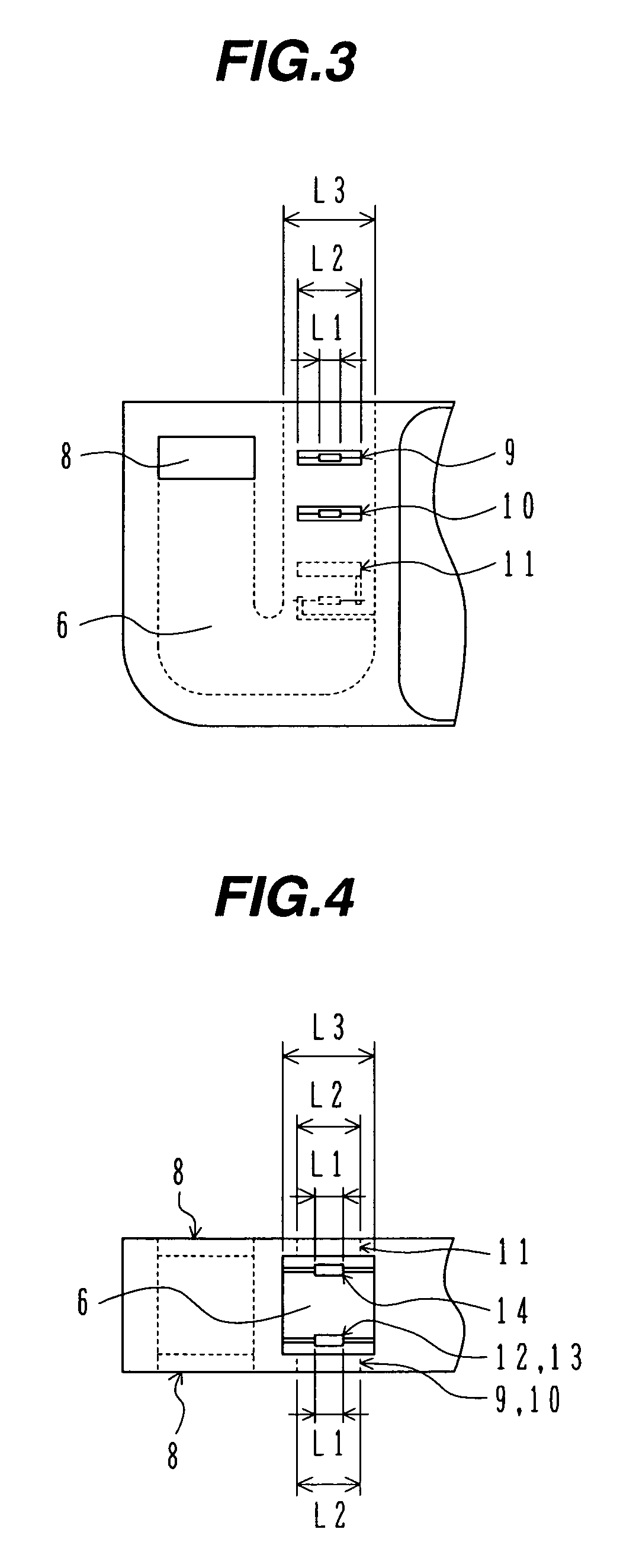
[0020]The construction of a flowmeter with a resistor heater according to one embodiment of the present invention will be described below with reference to FIGS. 1 to 11.

[0021]First, a description is made of an overall construction of the flowmeter with the resistor heater according to one embodiment of the present invention with reference to FIGS. 1 and 2.

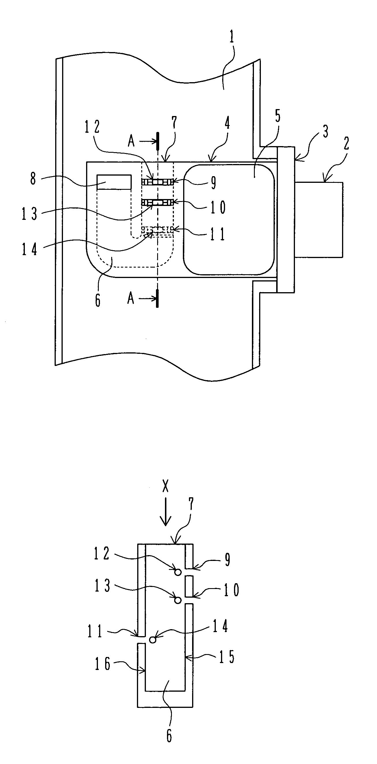
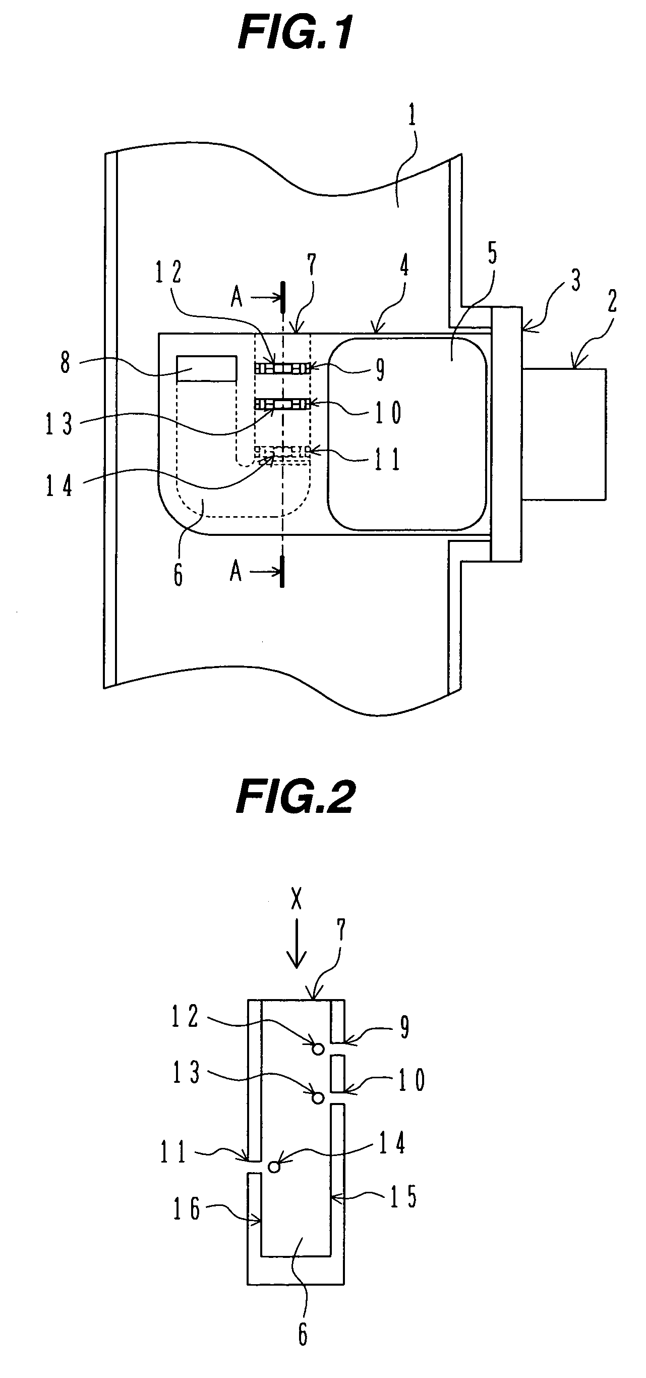
[0022]FIG. 1 is a longitudinal seeing-through sectional view showing the overall construction of the flowmeter with the resistor heater according to one embodiment of the present invention, and FIG. 2 is a longitudinal sectional view of an auxiliary passage of the flowmeter with the resistor heater according to one embodiment of the present invention, i.e., a sectional view taken along the line A—A in FIG. 1.

[0023]As shown in FIG. 1, a module housing 4 of the flowmeter with the resistor heater is mounted to an intake passage 1 of an automobile internal combustion engine through a module flange 3. A connector 2 for electrical conne...


PUM


Abstract

An air temperature detector 12 is disposed close to an auxiliary passage sidewall 15, which has an auxiliary passage wall hole 9 formed near the air temperature detector 12. A heat-sensitive resistor 13 is also disposed close to the auxiliary passage sidewall 15, which has an auxiliary passage wall hole 10 formed near the heat-sensitive resistor 13. Further, a resistor heater 14 is disposed close to an auxiliary passage sidewall 16, which has an auxiliary passage wall hole 11 near the resistor heater 14.

Description

TECHNICAL FIELD[0001]The present invention relates to an air flowmeter with a resistor heater for measuring the amount of intake air flowing through an intake passage of an internal combustion engine, and more particularly to a flowmeter with a resistor heater, which is suitable for measuring the flow rate of air sucked into an automobile engine.BACKGROUND ART[0002]It is known that conventional flowmeters with resistor heaters have various measurement errors. One of those measurement errors is a temperature characteristic error that occurs upon a detecting device, such as a resistor heater, heated by heat transmitted through a structure of the flowmeter with the resistor heater. Heat generating sources typically include 1) an engine and an exhaust pipe, and 2) a power transistor forming a signal amplification circuit in an electronic circuit section of the flowmeter with the resistor heater. There are possibly two heat transmission routes, i.e., A) one along which heat is transmitte...

Claims


Application Information

Patent Timeline
Patent Type & Authority Patents(United States)
IPC IPC(8): G01F1/68G01F1/684G01F1/69G01F5/00
CPCG01F1/6842G01F1/69G01F5/00
Inventor KIKAWA, HIROMUIGARASHI, SHINYAKOZAWA, MASAYUKISAITOU, NAOKISAITOU, TAKAYUKI
Owner HITACHI LTD
Why Eureka
Try Eureka