
Method for differential temperature rolling of composite strips based on actions of friction roller and device thereof

a friction roller and differential temperature technology, applied in the field of manufacturing metal composite strips, can solve the problems of low bonding strength of metal composite strips, prone to edge waves, middle waves and other problems in plate shapes, long process and heat loss, etc., to reduce temperature influence, shorten heat up time, and reduce heat loss

Pending Publication Date: 2022-05-19
TAIYUAN UNIV OF TECH
View PDF0 Cites 0 Cited by
  • Summary
  • Abstract
  • Description
  • Claims
  • Application Information

AI Technical Summary

Benefits of technology

The patent text describes the use of friction roller heating devices in the rolling process of a metal composite strip. This technology shortens the time needed to heat the strip, reduces heat loss, and regulates the speed of the friction rollers through temperature detection. The technology also allows for online accurate temperature control of the strip. Additionally, the metal surface is in contact with the friction roller to transfer heat from the surface to the entire metal, which reduces temperature effects between dissimilar metals and improves production efficiency. The friction force from the friction roller acts opposite to the rolling direction, creating tension that helps reduce the thickness of the strip and coordinately controls tension through displacement, rotation speed, and surface roughness of the friction roller.

Problems solved by technology

For dissimilar metal rolled composite strip, the common problem is that the deformation resistance of dissimilar metals under identical temperature conditions is different, which makes the deformation of dissimilar metals inconsistent, resulting in low bonding strength of the metal composite strip, and prone to edge waves, middle waves and other problems in plate shapes.
The first method has problems such as lengthy process and heat loss.
Electromagnetic induction heating is only suitable for paramagnetic metals, and the heating speed is slow for other metals.
In short, the above-mentioned methods for differential temperature rolling of composite strip has problems such as large energy consumption, complicated and cumbersome procedures and are greatly limited in application.

Method used


Image

  • Method for differential temperature rolling of composite strips based on actions of friction roller and device thereof
  • Method for differential temperature rolling of composite strips based on actions of friction roller and device thereof
  • Method for differential temperature rolling of composite strips based on actions of friction roller and device thereof

Examples


embodiment 1

[0031]Taking the differential temperature rolled magnesium-aluminum composite strip as an example, the width of the magnesium strip and the aluminum strip are both 60 mm, a thickness of the magnesium strip and the aluminum strip are both 0.5 mm, the magnesium strip is on the top, and the aluminum strip is on the bottom.

[0032]A method for different temperature rolling of composite strips based on the action of a friction roller comprises the following steps:

[0033]S1. preparing magnesium strips and aluminum strips, and performing surface treatment respectively on surfaces of the magnesium strips and aluminum strips to be bonded;

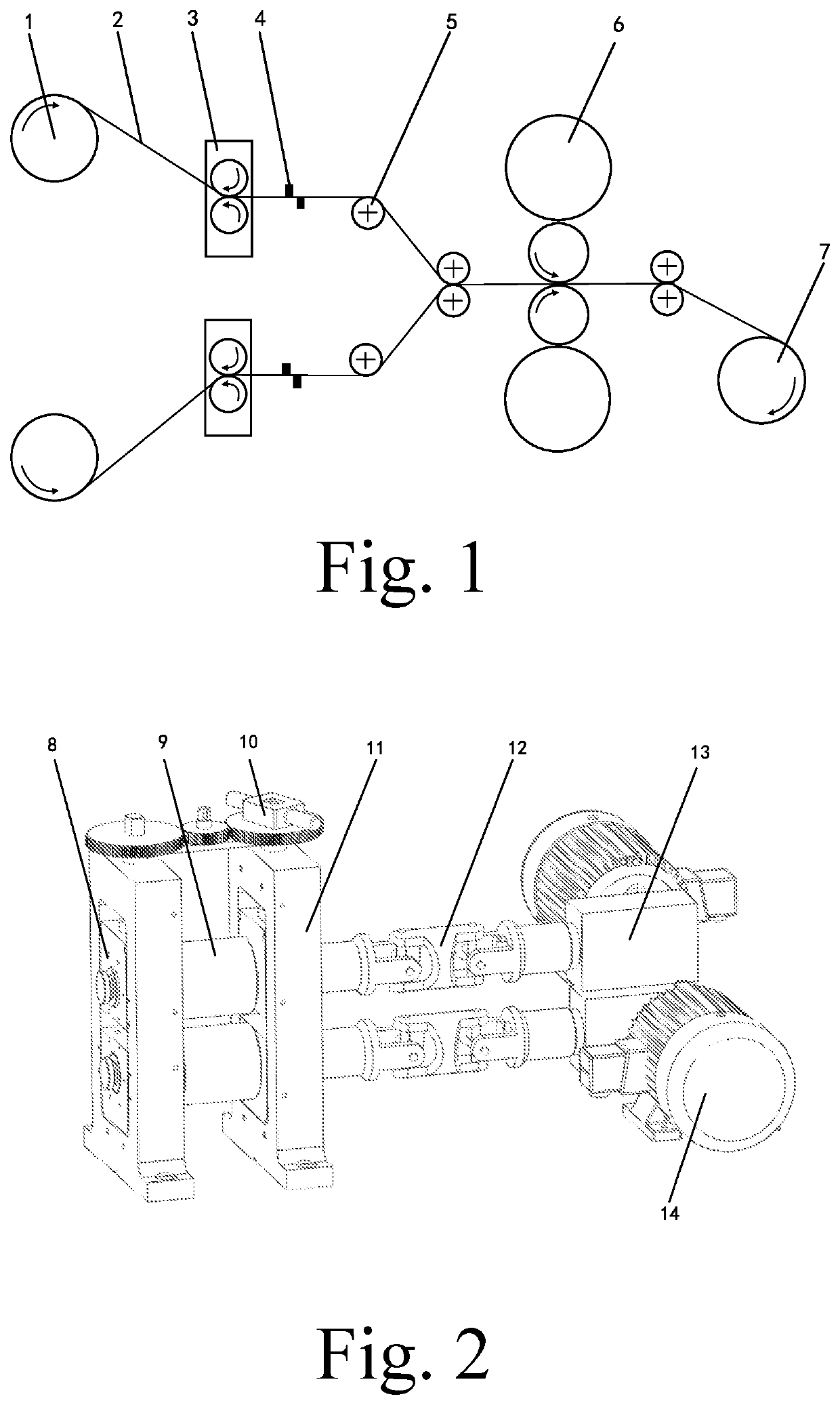
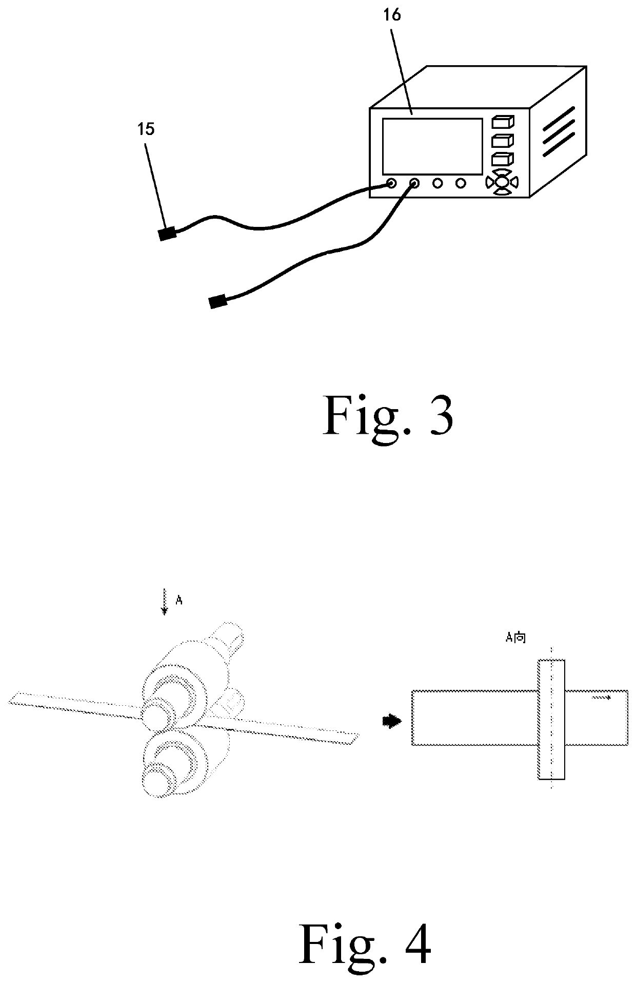
[0034]S2. frictionally heating the magnesium strip by several sets of friction roller heating devices 3, measuring a surface temperature of the magnesium strip after friction heating by a temperature detector 4, and adjusting the friction roller 9 in the friction roller heating device 3 according to the measured temperature; wherein a rotation speed is adjusted...

embodiment 2

[0038]Taking the differential temperature rolled steel-copper composite strip as an example, a width and thickness of the steel strip are 40 mm and 0.6 mm respectively, and a width and thickness of the copper strip are 40 mm and 1.5 mm respectively, with the copper strip on the top and the steel strip on the bottom.

[0039]A method for different temperature rolling of composite strips based on the action of a friction roller comprises the following steps:

[0040]S1. preparing copper strips and steel strips, and performing surface treatment on surfaces of the copper strips and steel strips to be bonded;

[0041]S2. frictionally heating the copper strip and steel strip by several sets of friction roller heating devices 3, and the surface temperature of the copper strips and steel strips after friction heating is measured by the temperature detector 4, and the friction roller is adjusted according to the measured temperature; wherein the rotating speed of the friction roller 9 in the heating ...


PUM

PropertyMeasurementUnit
included angleaaaaaaaaaa
thicknessaaaaaaaaaa
thicknessaaaaaaaaaa

Abstract

The present invention relates to the technical field of fabricating a metal composite strip, and specifically relates to a method for differential temperature rolling of composite strips based on actions of a friction roller and a device thereof. A method for differential temperature rolling of composite strips based on actions of a friction roller comprises steps of: S1: preparing a metal strip to be bonded, and performing surface treatment on the metal strip to be bonded; S2: frictionally heating the metal strip to be bonded by several sets of friction roller heating devices; measuring a surface temperature of the friction-heated metal strip to be bonded strip by a temperature detector; according to a measured temperature, adjusting a rotation speed of the friction roller in the friction roller heating devices; and S3: transporting the heated metal strip to be bonded to a rolling mill for rolling to obtain a metal composite strip. The invention adopts the friction roller heating devices in rolling process of the metal strip to be bonded, utilizes the friction heat generation effect of the high-speed rotating friction roller and the metal strip to be bonded, and generates different heat in the dissimilar metals by adjusting the speed of the friction roller, thereby generating different temperature rise to realize different temperature rolling of the metal composite strips.

Description

CROSS REFERENCE OF RELATED APPLICATION[0001]This is a Continuation application of an International Application PCT / CN2020 / 136955, filed Dec. 16, 2020, which claims priority under 35 U.S.C. 119(a-d) to CN202011119639.3, filed Oct. 19, 2020.BACKGROUND OF THE PRESENT INVENTIONField of Invention[0002]The present invention relates to the technical field of fabricating metal composite strips, and specifically relates to a method for differential temperature rolling of composite strips based on actions of a friction roller and a device thereof.Description of Related Arts[0003]Metal composite strip is a laminated composite material with both structure and functionality, which has a variety of excellent metal properties. In recent years, metal composite strip has been widely used in petrochemical, aerospace, national defense industry, transportation and household appliances, etc. The promotion and application of the metal laminated composite strip is of great significance to solve the promin...

Claims


Application Information

Patent Timeline
Patent Type & Authority Applications(United States)
IPC IPC(8): B21B45/00B21B1/38
CPCB21B45/004B21B1/38B21B1/22B21B2001/225B21B2001/383
Inventor WANG, TAOWANG, CHANGJIANGWU, YUECHEN, PENGHAN, JIANCHAOREN, ZHONGKAILIU, YUANMINGHUANG, QINGXUE
Owner TAIYUAN UNIV OF TECH
Learn More