Diffusion sheet structure

Pending Publication Date: 2021-11-04
TCL CHINA STAR OPTOELECTRONICS TECH CO LTD
View PDF0 Cites 0 Cited by
  • Summary
  • Abstract
  • Description
  • Claims
  • Application Information

AI Technical Summary

Benefits of technology

[0027]The technical effect of the present disclosure is to use Janus material in a diffusion sheet to replace diffusion particles of prior art, which not only retains original function of diffusing light, but also has excellent thermal condu

Problems solved by technology

Furthermore, the closer to the lamp tube, the more severe the heat, causing temperature of the liquid crystal display panel in an entire backlight plate to have temperature diffe

Method used


Image

  • Diffusion sheet structure
  • Diffusion sheet structure

Examples


Embodiment Construction

[0031]In order to allow the above and other purposes, features, and advantages of the present disclosure to be more obvious and easy to understand, preferred embodiments of the present disclosure will be particularly described hereinafter, and with reference to the accompanying drawings, a detailed description will be given below. Furthermore, directional terms described by the present disclosure, such as upper, lower, top, bottom, front, rear, left, right, inner, outer, side, circumference, center, horizontal, vertical, axial, radial, top layer, bottom layer, etc., are only directions by referring to the accompanying drawings. Therefore, the adopted directional terms are used to describe and understand the present disclosure, but the present disclosure is not limited thereto.

[0032]In the figures, units with similar structures are indicated by the same reference numerals.

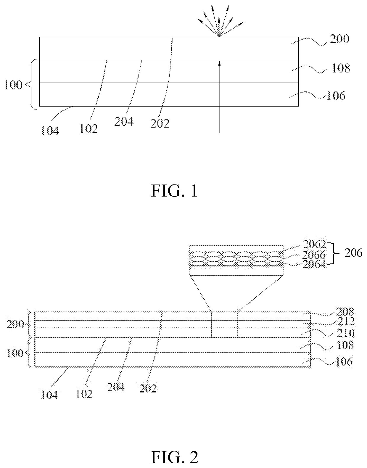
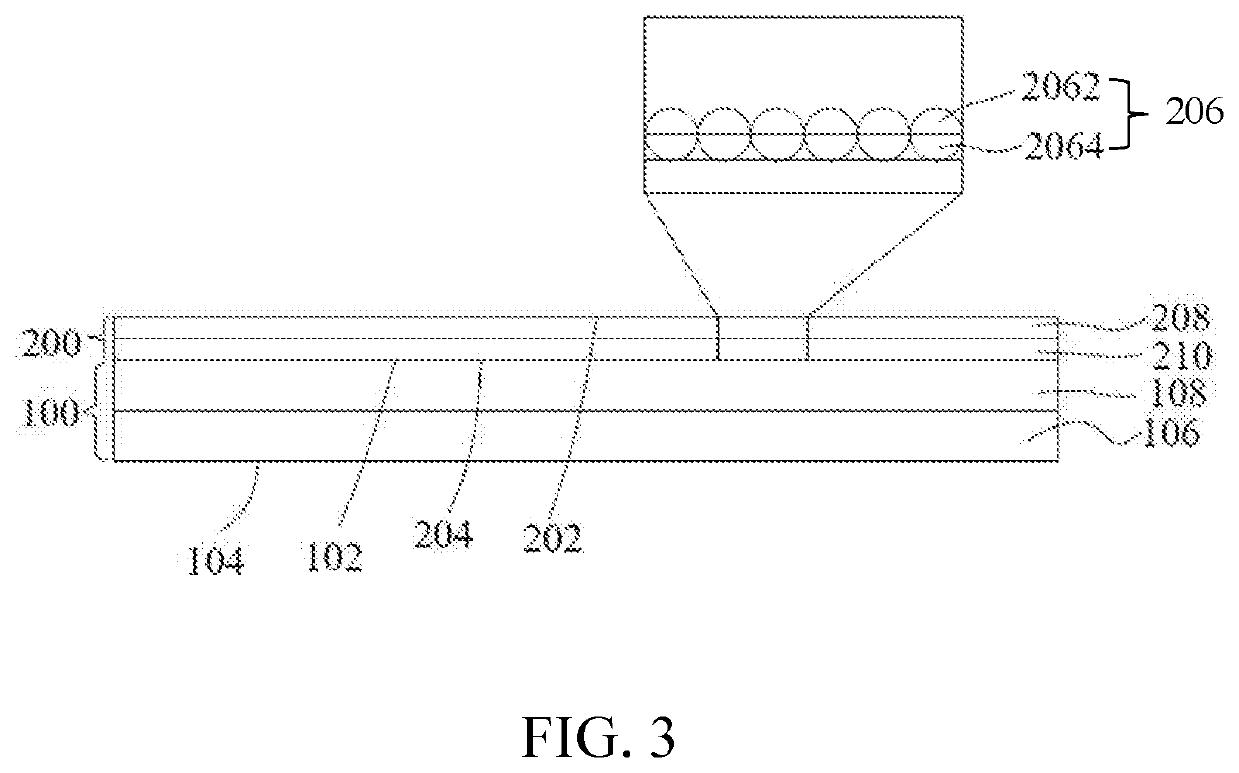
[0033]Please refer to FIG. 1 to FIG. 3, FIG. 1 to FIG. 3 area first to a third schematic diagrams of a diffusion ...


PUM


Abstract

A diffusion sheet structure includes a transparent substrate and a diffusion film. The transparent substrate includes a first upper surface and a first lower surface. The diffusion film is disposed on the transparent substrate and includes a plurality of nano diffusion particles, and has a second upper surface and a second lower surface. The second lower surface is connected to the first upper surface. Janus material in a diffusion sheet is used in the present disclosure to replace diffusion particles of prior art, which not only retains original function of diffusing light, but also has excellent thermal conductivity, thereby improving thermal uniformity, making the liquid crystal display panel be heated uniformly, and reducing influence of temperature on liquid crystal material during lighting, thereby improving the problem of local area whitening.

Description

FIELD OF INVENTION[0001]The present disclosure relates to the field of display technology, and particularly relates to a diffusion sheet structure using Janus material.BACKGROUND OF INVENTION[0002]Generally, liquid crystal display devices include liquid crystal display panels and backlight modules for providing light sources. The backlight modules include lamp tubes, light guide plates, reflective sheets, etc. The lamp tube is primarily for realizing a light emitting purpose, and the diffusion sheet primarily makes emitted light be uniformly diffused to each direction by several diffusion particles to improve uniformity of light distribution.[0003]During a process of the backlight module continuously lighting up, the lamp tube heats up, which increases a temperature of the backlight module. Furthermore, the closer to the lamp tube, the more severe the heat, causing temperature of the liquid crystal display panel in an entire backlight plate to have temperature difference, and the te...

Claims


Application Information

Patent Timeline
IPC IPC(8): G02F1/13357G02F1/1335G02B5/02
CPCG02F1/133606G02F1/133628G02B2207/101G02B5/0278G02B5/0226G02B5/0242G02F1/133602G02F1/133609G02F1/133611G02B5/0294
Inventor LI, QIAN
Owner TCL CHINA STAR OPTOELECTRONICS TECH CO LTD
Why Eureka
Try Eureka