Electrode Assembly Having Tab-Lead Joint Portion of Minimized Resistance Difference Between Electrodes and Electrochemical Cell Containing The Same

a technology of resistance difference and electrode, which is applied in the direction of battery, sustainable manufacturing/processing, cell components, etc., can solve the problems of reducing the life span of the battery, and affecting the efficiency of the battery life, so as to achieve the effect of minimizing the resistance difference between the electrodes and high reliability

Inactive Publication Date: 2009-12-24
LG CHEM LTD
View PDF4 Cites 31 Cited by
  • Summary
  • Abstract
  • Description
  • Claims
  • Application Information

AI Technical Summary

Benefits of technology

[0013]Specifically, it is an object of the present invention to provide an electrode assembly having a structure in which the resistance difference between electrodes is minimized.
[0014]It is another object of the present invention to provide an electrode assembly having a structure in which the joint force between electrode tabs and each electrode lead is increased, whereby high reliability is secured.

Problems solved by technology

Due to this joint structure, however, the resistance difference between the electrodes with respect to each electrode lead may occur in the electrode assembly.
Consequently, the electrodes may be nonuniformly operated or deteriorated, due to the resistance difference between the electrodes, which may reduce the life span of the battery.

Method used


Image

  • Electrode Assembly Having Tab-Lead Joint Portion of Minimized Resistance Difference Between Electrodes and Electrochemical Cell Containing The Same
  • Electrode Assembly Having Tab-Lead Joint Portion of Minimized Resistance Difference Between Electrodes and Electrochemical Cell Containing The Same
  • Electrode Assembly Having Tab-Lead Joint Portion of Minimized Resistance Difference Between Electrodes and Electrochemical Cell Containing The Same

Examples


example 1

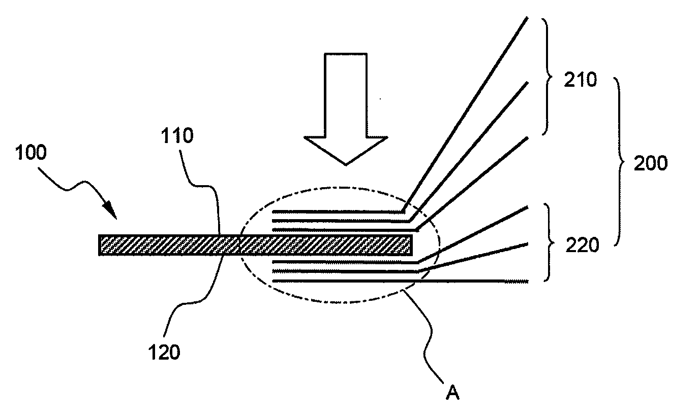
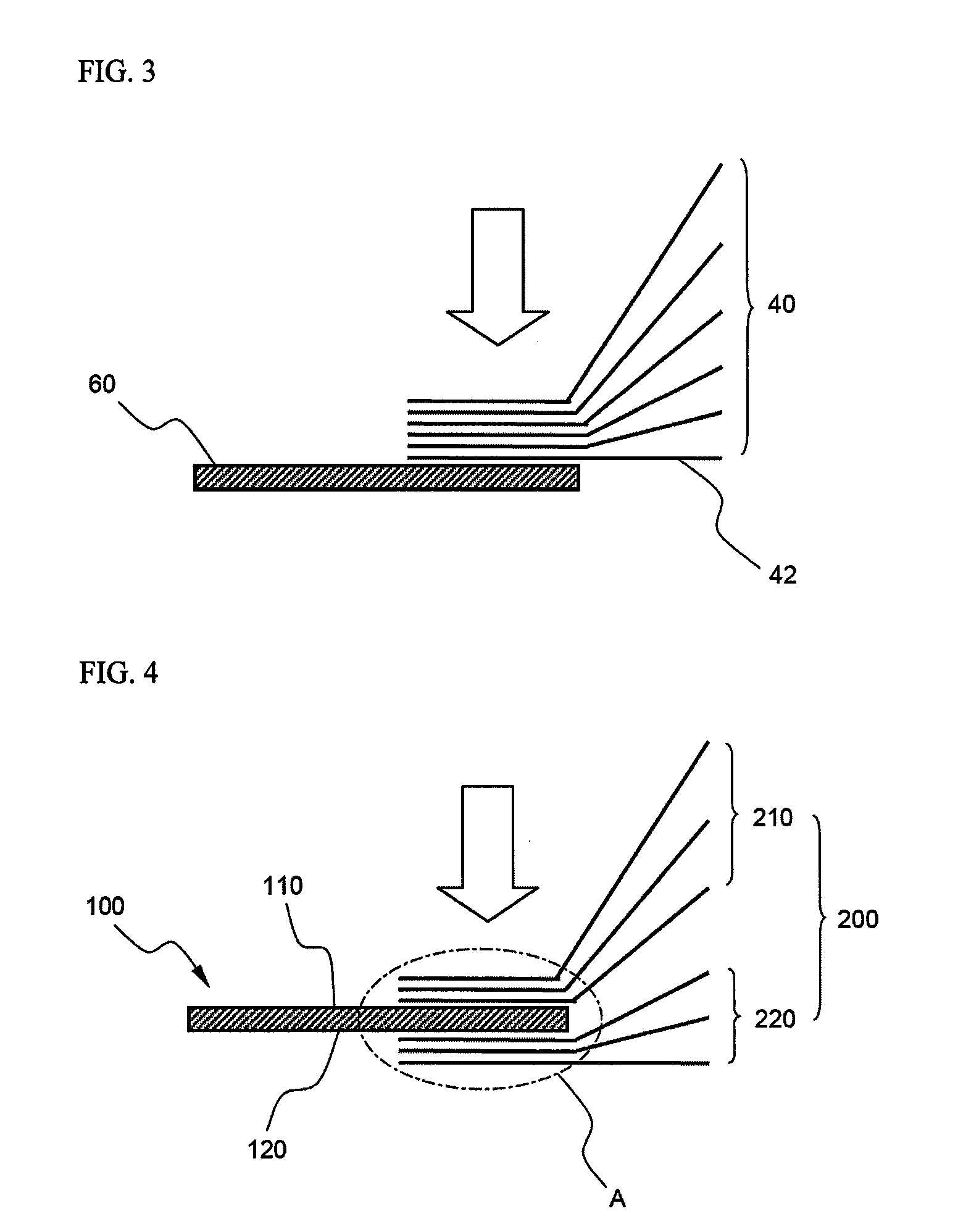
[0031]A cathode active material containing lithium and an anode active material containing graphite were applied to opposite major surfaces of an aluminum foil and a copper foil, respectively, and then the aluminum foil and the copper foil were cut to manufacture cathode plates and anode plates, having electrode tabs to which the active materials were not applied. Subsequently, the cathode plates and the anode plates were sequentially stacked while separators were disposed respectively between the cathode plates and the anode plates. After that, a cathode lead was welded to the cathode tabs, while the cathode lead was disposed between the cathode tabs, and an anode lead was welded to the anode tabs, while the anode lead was disposed between the anode tabs, as shown in FIG. 4, to manufacture an electrode assembly.

experimental example 1

[0033]Resistance measurement experiments were carried out on 20 electrode assemblies manufactured respectively according to Example 1 and Comparative example 1. The experiment results are indicated in Table 1 below. The experiments were repeatedly carried out on the respective 20 electrode assemblies. The resistance at the joint portion between the cathode tabs and the cathode lead was measured using an Agilent milli-ohmmeter. The measured experiment values are indicated in Table 1 below as an average resistance value.

[0034]Group A of Table 1 below indicates the cathode tabs located at the upper part of the electrode assembly. For Example 1, Group A indicates the cathode tabs located at the top of the cathode lead. For Comparative example 1, Group A indicates the cathode tabs at long distances from the cathode lead. Group B of Table 1 below indicates the cathode tabs located at the lower part of the electrode assembly. For Example 1, Group B indicates the cathode tabs located at the...


PUM

PropertyMeasurementUnit
resistanceaaaaaaaaaa
shapeaaaaaaaaaa
energy densityaaaaaaaaaa

Abstract

Disclosed herein is a stacking or stacking/folding type electrode assembly of a cathode/separator/anode structure, wherein the electrode assembly is constructed in a structure in which tabs (electrode tabs), having no active material applied thereto, protrude from electrode plates constituting the electrode assembly, the electrode tabs are electrically connected to an electrode lead, and the pluralities of electrode tabs are joined to the top and the bottom of the electrode lead at an electrode lead-electrode tabs joint portion such that the resistance difference between electrodes at the electrode lead-electrode tabs joint portion is minimized. Also disclosed is an electrochemical cell including the electrode assembly.

Description

FIELD OF THE INVENTION[0001]The present invention relates to an electrode assembly having a tab-lead joint portion of minimized resistance difference between electrodes, and, more particularly, to a stacking or stacking / folding type electrode assembly of a cathode / separator / anode structure, wherein the electrode assembly is constructed in a structure in which tabs (electrode tabs), having no active material applied thereto, protrude from electrode plates constituting the electrode assembly, the electrode tabs are electrically connected to an electrode lead, and the pluralities of electrode tabs are joined to the top and the bottom of the electrode lead at an electrode lead-electrode tabs joint portion such that the resistance difference between electrodes at the electrode lead-electrode tabs joint portion is minimized.BACKGROUND OF THE INVENTION[0002]As mobile devices have been increasingly developed, and the demand for such mobile devices has increased, the demand for batteries has...

Claims


Application Information

Patent Timeline
Patent Type & Authority Applications(United States)
IPC IPC(8): H01M4/02H01G11/22H01G11/66H01G11/72H01G11/74H01G11/76H01G11/78H01M10/052H01M10/0583H01M50/119H01M50/121H01M50/124H01M50/528H01M50/533H01M50/534H01M50/536H01M50/54
CPCH01M2/26Y02E60/122H01M10/04H01M2/266Y02E60/10H01M50/54Y02P70/50H01M50/121H01M50/534H01M50/124H01M50/536H01M50/533H01M50/119H01G11/26H01G11/72H01M10/052H01M10/0583H01M10/0585H01G11/06H01M10/0459H01M10/0413H01M2220/20H01M2220/10H01M50/531H01M2220/30
Inventor RYU, JI HEONCHOI, JEONG HEEYOO, KWANGHOSHIN, YOUNGJOON
Owner LG CHEM LTD
Why Eureka
Try Eureka