Blood pressure monitoring system

a monitoring system and blood pressure technology, applied in the field of blood pressure devices, can solve the problems of difficult transport of these systems, large prior art devices,

Inactive Publication Date: 2009-12-24
WELCH ALLYN INC
View PDF20 Cites 38 Cited by
  • Summary
  • Abstract
  • Description
  • Claims
  • Application Information

AI Technical Summary

Benefits of technology

[0004]It is a primary object of the present invention to improve non-invasive blood pressure devices and, in particular, monitors that are capable of automatically taking a patients blood pressure.
[0005]A further object of the present invention is to eliminate the need of sharing a common blood pressure cuff between a number of patients.
[0006]Another object of the present invention is to eliminate the need for loose pneumatic and electrical lines running between the components of an automatic blood pressure monitor.
[0007]These and other objects of the current invention are attained by a blood pressure device that includes a compact housing that contains a pneumatic circuit that is attached to a

Problems solved by technology

These prior art devices, however, tend to be rather large and have external tubing and electrical wires interconnect the various components of the system.
However, because of the number of tubes and wire involved, the transporting of these systems

Method used


Image

  • Blood pressure monitoring system
  • Blood pressure monitoring system
  • Blood pressure monitoring system

Examples


Embodiment Construction

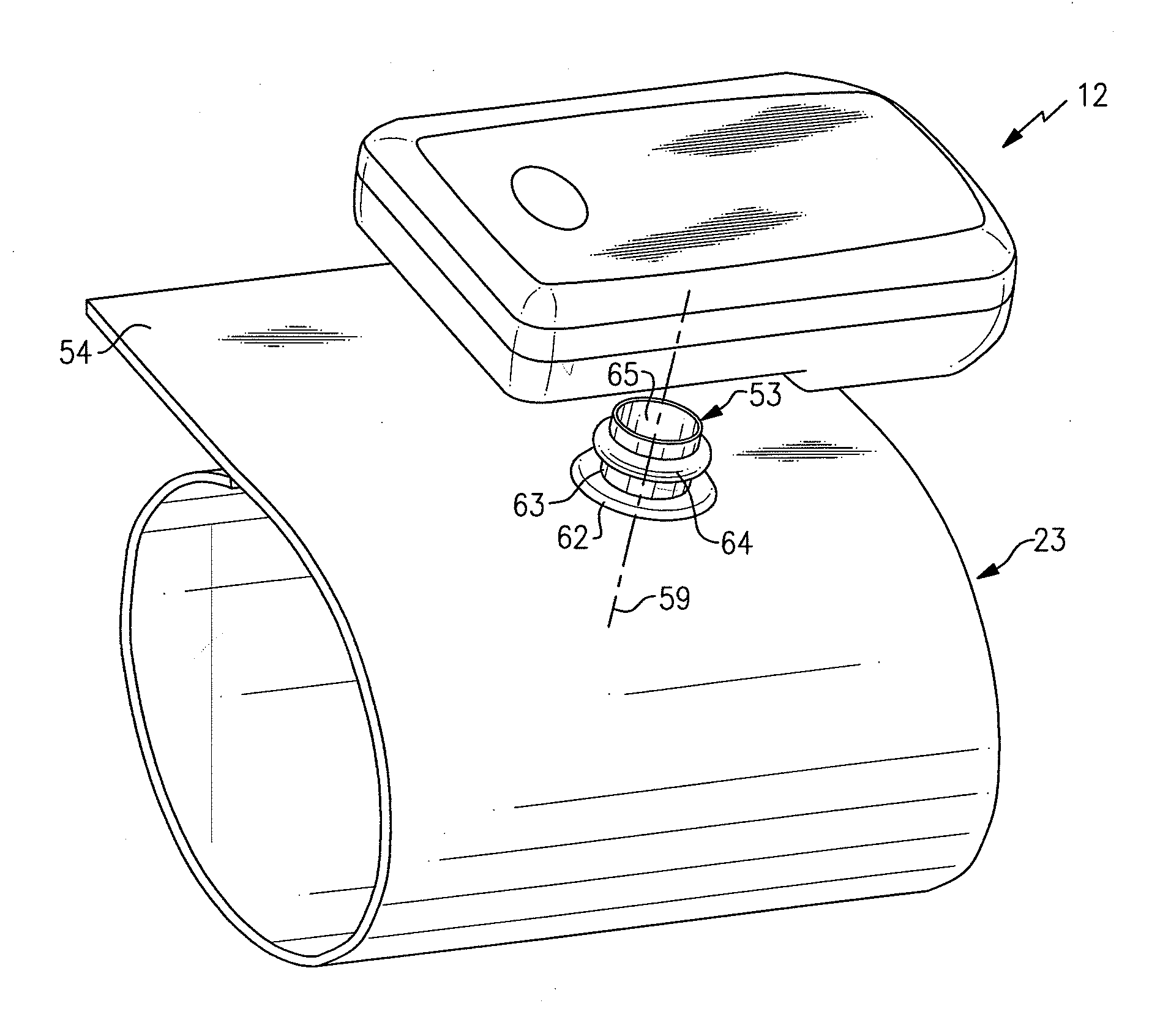
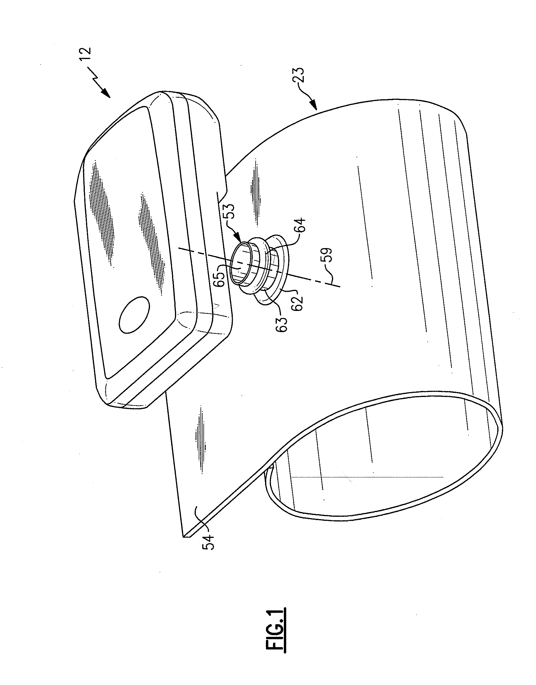
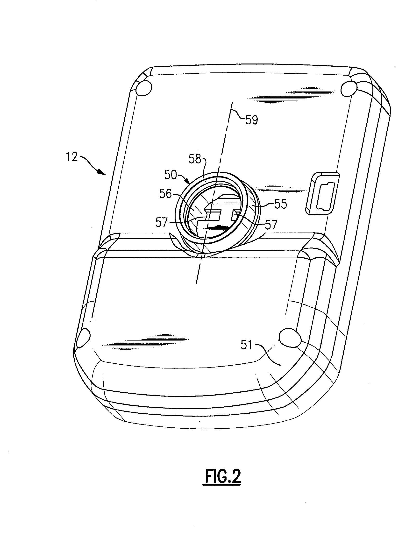
[0013]A blood pressure system, generally referenced 10, that embodies the present invention is shown schematically in FIG. 4. The system 10 includes a small compact housing 12 that contains a three element pneumatic circuit 13. The pneumatic circuit includes a pump 15, an exhaust valve 16 and a pressure sensor 17. The elements of the pneumatic circuit are all connected to a common pneumatic line 19 which, in turn, is coupled to one part 50 of a two piece connector that is generally referenced 20. As will be explained in further detail below, the other part of the connector 53 is attached to a non-invasive blood pressure cuff 23.

[0014]Also contained in the housing 12 is a controller 25 which is a microprocessor that can be programmed to control the pump and valve to inflate and deflate the cuff and to receive pressure related data from the pressure sensor. The controller is coupled to a wireless bi-directional communication unit 26 which links the controller to a remote host station ...


PUM


Abstract

A blood pressure monitoring system that includes a compact housing that contains a pneumatic circuit that is removably attached to an inflatable cuff by a hoseless connector so that the cuff can be inflated and deflated to provide blood pressure readings that are detected by a pressure sensor. A controller is also contained in the housing which controls the circuit activities and records blood pressure related data. The controller is linked via a bidirectional communication system with a processor that is contained in a host station which programs the controller and collects and records blood pressure related data. The communication system also allows the monitoring system to communicate over a wider network with other remote stations.

Description

FIELD OF THE INVENTION[0001]This invention relates to a blood pressure device and, in particular, to a blood pressure system that provides a flexible and low cost platform for automatically performing a non-invasive procedure without the need of external interconnections such as pneumatic tubes and electrical wiring.BACKGROUND OF THE INVENTION[0002]Non-invasive blood pressure devices generally utilize an inflatable cuff to measure a patients blood pressure. The cuff is affixed to a limb over an artery and is then inflated to constrict the flow of blood through the artery. Blood passing through the constrained vessel produces changes in the cuff pressure which can be measured by a pressure sensor to give an indication of the condition of the patients heart. Two pressures of specific interest are the systolic pressure and the diastolic pressure. Systolic pressure is the maximum arterial pressure produced during the contraction of the left ventricle of the heart. The diastolic pressure...

Claims


Application Information

Patent Timeline
IPC IPC(8): A61B5/02A61B5/00
CPCA61B5/02233A61B2560/0443A61B5/0002A61B5/0225
Inventor WHITAKER, TYSON B.KINSLEY, MATTHEW J.LANE, JOHN A.MARTIN, SCOTT A.GRANT, THOMAS J.MEYER, STEPHEN F.
Owner WELCH ALLYN INC
Why Eureka
Try Eureka