Output shaft reduction-type dual clutch transmission

Active Publication Date: 2009-12-31
ISUZU MOTORS LTD
View PDF9 Cites 55 Cited by
  • Summary
  • Abstract
  • Description
  • Claims
  • Application Information

AI Technical Summary

Benefits of technology

[0022]As described in claim 3, further, the first input shaft is hollow, the second input shaft extends passing through the hollow portion of the first input shaft, and the output shaft is arranged in concentric with the first input shaft and the second input shaft. Upon employing the above constitution, the dual clutch transmission is constructed in a compact size and, particularly

Problems solved by technology

A torque converter in the automatic transmission is a transmission device that utilizes a fluid involving, however, a loss of power transmission.
Besides, the planetary gear mechanism and a control device, therefore, are complex and expensive.
On the other hand, an automatic speed-changing device that uses the transmission of the type of parallel shaft gear mechanism tends to produce a larger shock of change at the time of shifting the transmission steps than that of the automatic transmission.
At this mom

Method used


Image

  • Output shaft reduction-type dual clutch transmission
  • Output shaft reduction-type dual clutch transmission
  • Output shaft reduction-type dual clutch transmission

Examples


Example

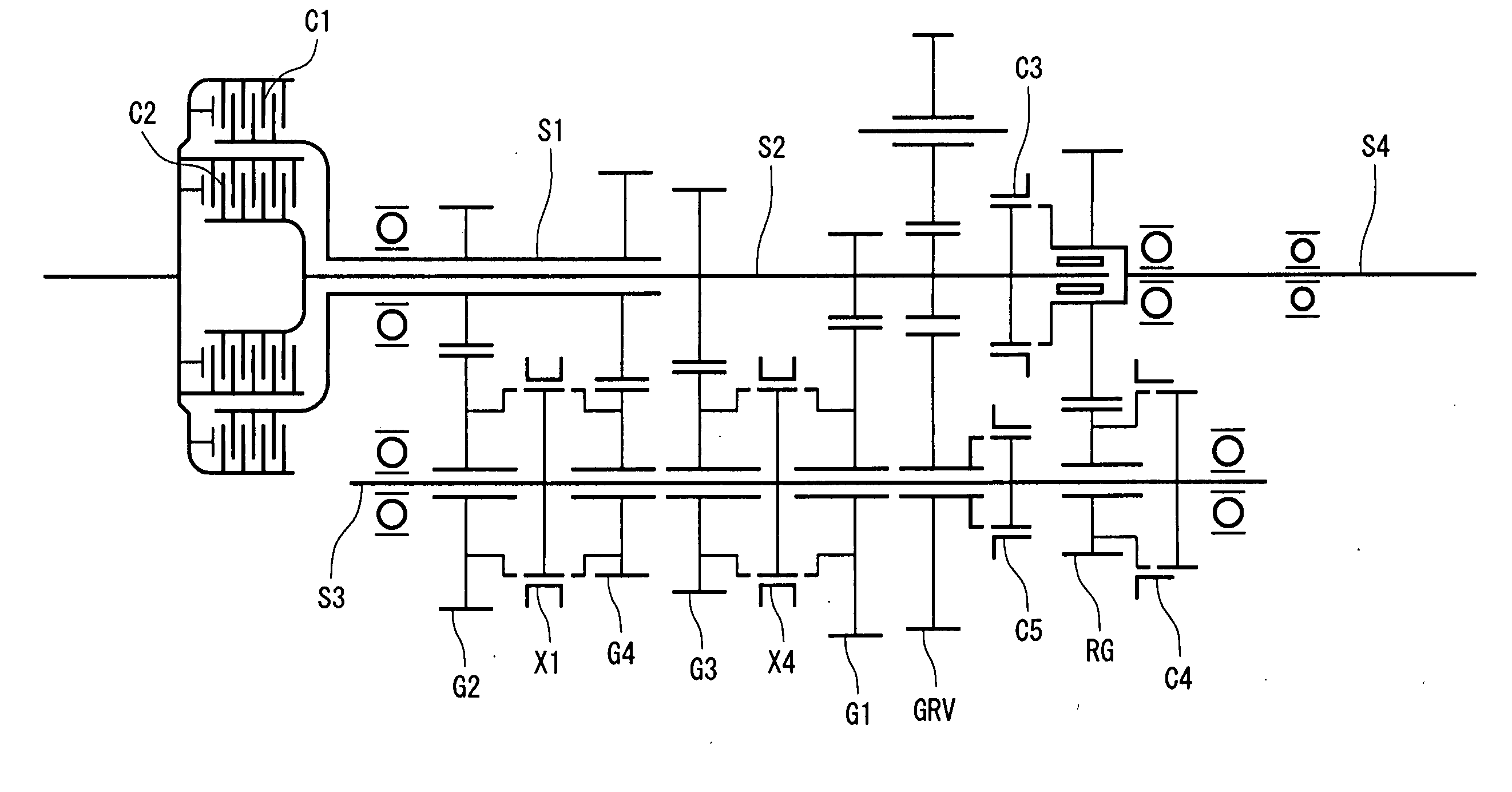
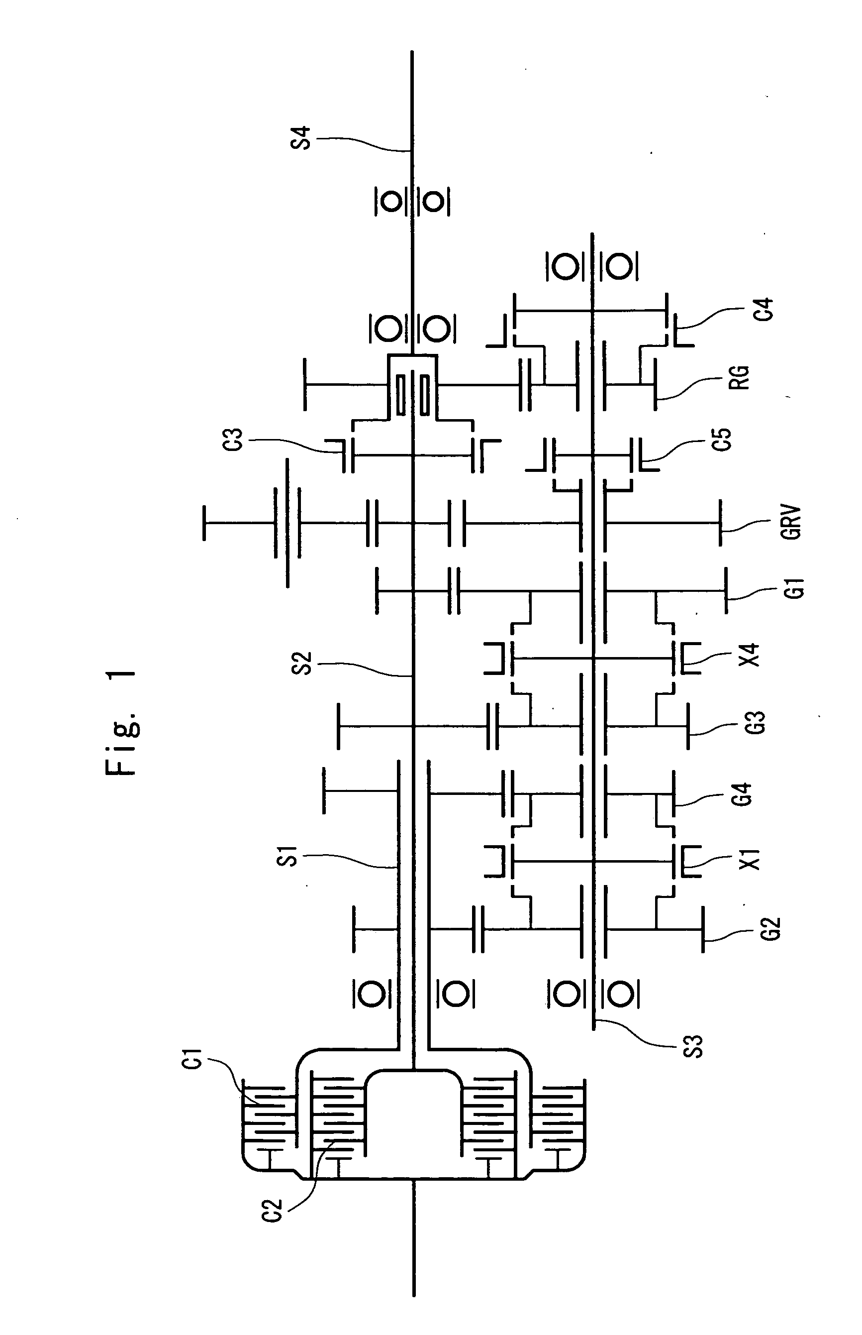
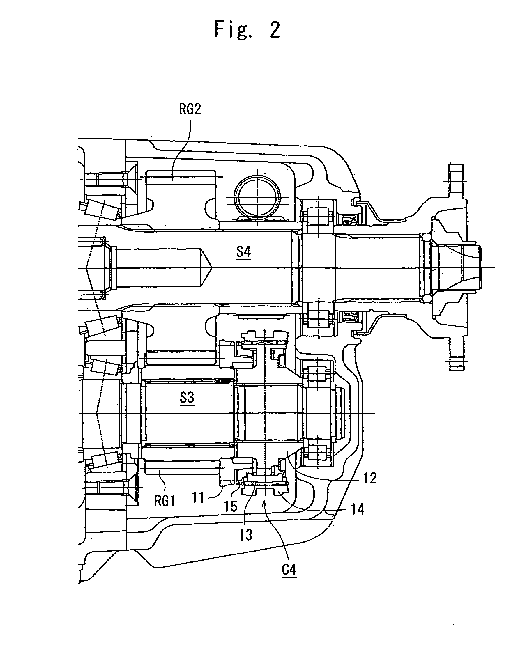
[0028]The dual clutch transmission of the invention will now be described with reference to the drawings. FIG. 1 is a view schematically illustrating the whole dual clutch transmission of the present invention, FIG. 2 is a view illustrating, in detail, the vicinities of an output shaft reduction gear train on which the intermediate shaft connection clutch of the invention is placed, and FIG. 3 is a view illustrating a transmission step shifting device. In these drawings, the parts corresponding to those of the conventional dual clutch transmission shown in FIG. 5 are denoted by the same reference numerals.

[0029]The basic structure and operation of the dual clutch transmission of the present invention are the same as those of the conventional dual clutch transmission of the output reduction type described with reference to FIG. 5. That is, as shown in FIG. 1, the dual clutch transmission has a first clutch C1 and a second clutch C2 arranged in concentric, the first clutch C1 being co...


PUM


Abstract

A dual clutch transmission having two input shafts respectively connected to clutches, and an intermediate shaft, preventing the intermediate shaft from rotating idle when the vehicle is traveling at high speeds and avoiding excess stirring of lubricating oil in the transmission and increase in noise. In the dual clutch transmission, a direct connection clutch C3 is provided between one input shaft S2 and an output shaft S4, and an intermediate shaft connection clutch C4 for interrupting the transmission of power is provided between the intermediate shaft S3 and the output shaft S4. When the power is directly transmitted from the input shaft S2 to the output shaft S4 via the direct connection clutch C3, the intermediate shaft connection clutch C4 is disconnected to stop the rotation of the intermediate shaft S3 and to prevent the lubricating oil from being excessively stirred by the idle rotation of the intermediate shaft S3. Further, the intermediate shaft connection clutch C4 is disconnected, and a transmission step is constituted by utilizing the gear trains among the two input shafts and the intermediate shaft S3, making it possible to omit one gear train and, therefore, to shorten the length of the transmission.

Description

TECHNICAL FIELD[0001]This invention relates to a transmission in a power transmission device of a vehicle. More specifically, the invention relates to a transmission having two clutches and two transmission input shafts connected to the respective clutches, and automatically connects and disconnects these clutches at the time of shifting the transmission steps.BACKGROUND ART[0002]A variety of kinds of automatic power transmission devices have been developed for the vehicles in order to facilitate the driving of a vehicle and to reduce fatigue to the driver. A representative example may be an automatic transmission comprising a torque converter and a planetary gear mechanism in combination, as is widely used as the power transmission device for the so-called automatic transmission vehicles (AT vehicles). In addition to the automatic transmission, there is a power transmission device by using a transmission of the type of parallel shaft gear mechanism similar to that of a manual trans...

Claims


Application Information

Patent Timeline
IPC IPC(8): F16H3/08
CPCF16H3/006F16H3/0915Y10T74/19228F16H2200/0056Y10T74/19223F16H2200/0052
Inventor AKASHI, KOUHEIIKEDA, TADASHI
Owner ISUZU MOTORS LTD
Why Eureka
Try Eureka