

Variable valve mechanism
a valve mechanism and variable technology, applied in the direction of valve arrangements, mechanical equipment, machines/engines, etc., to achieve the effect of accurate prescribing of relative angles, high precision, and adjustment of operating angles
- Summary
- Abstract
- Description
- Claims
- Application Information
AI Technical Summary
Benefits of technology
Problems solved by technology
Method used
Image

Examples
first embodiment
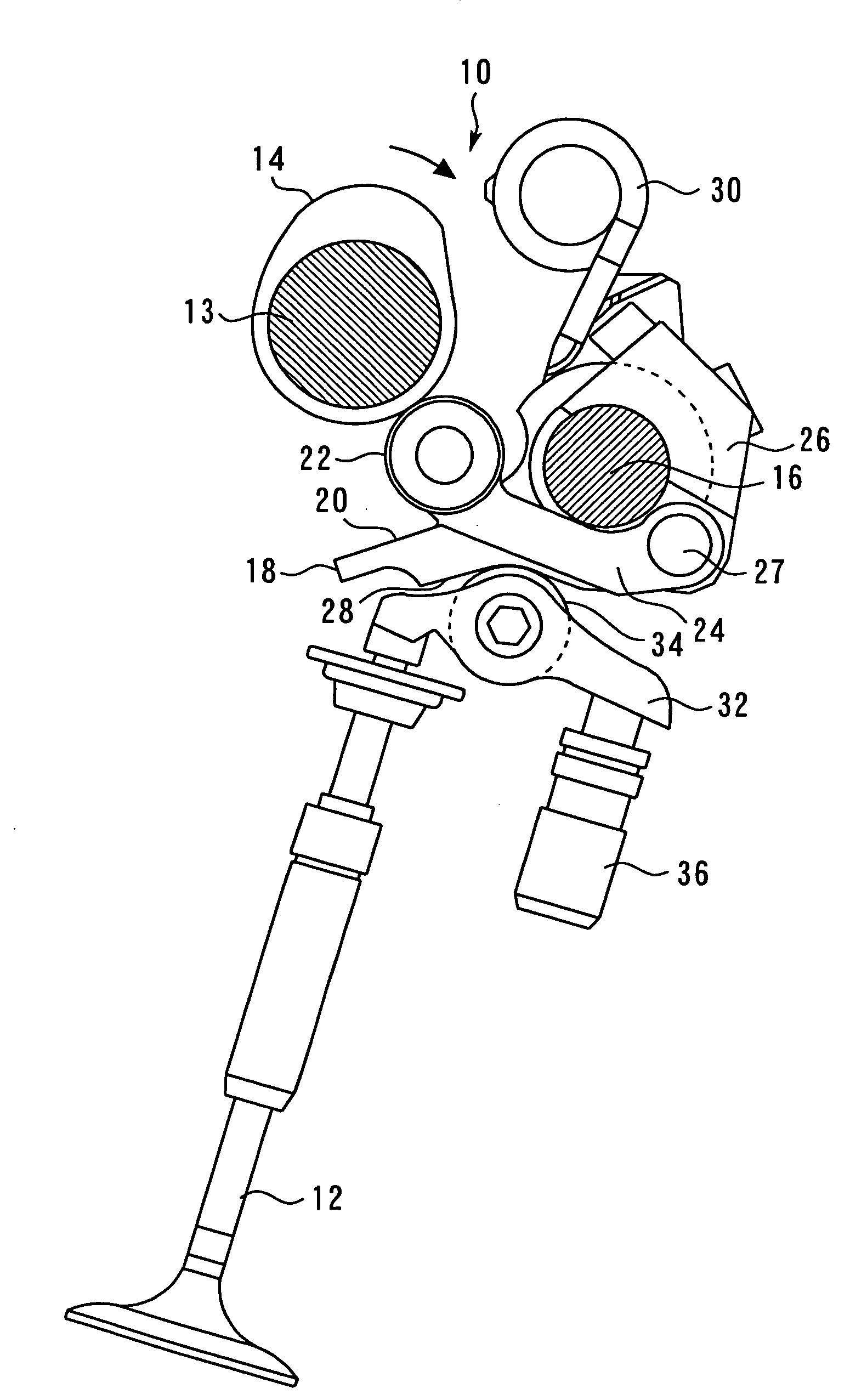
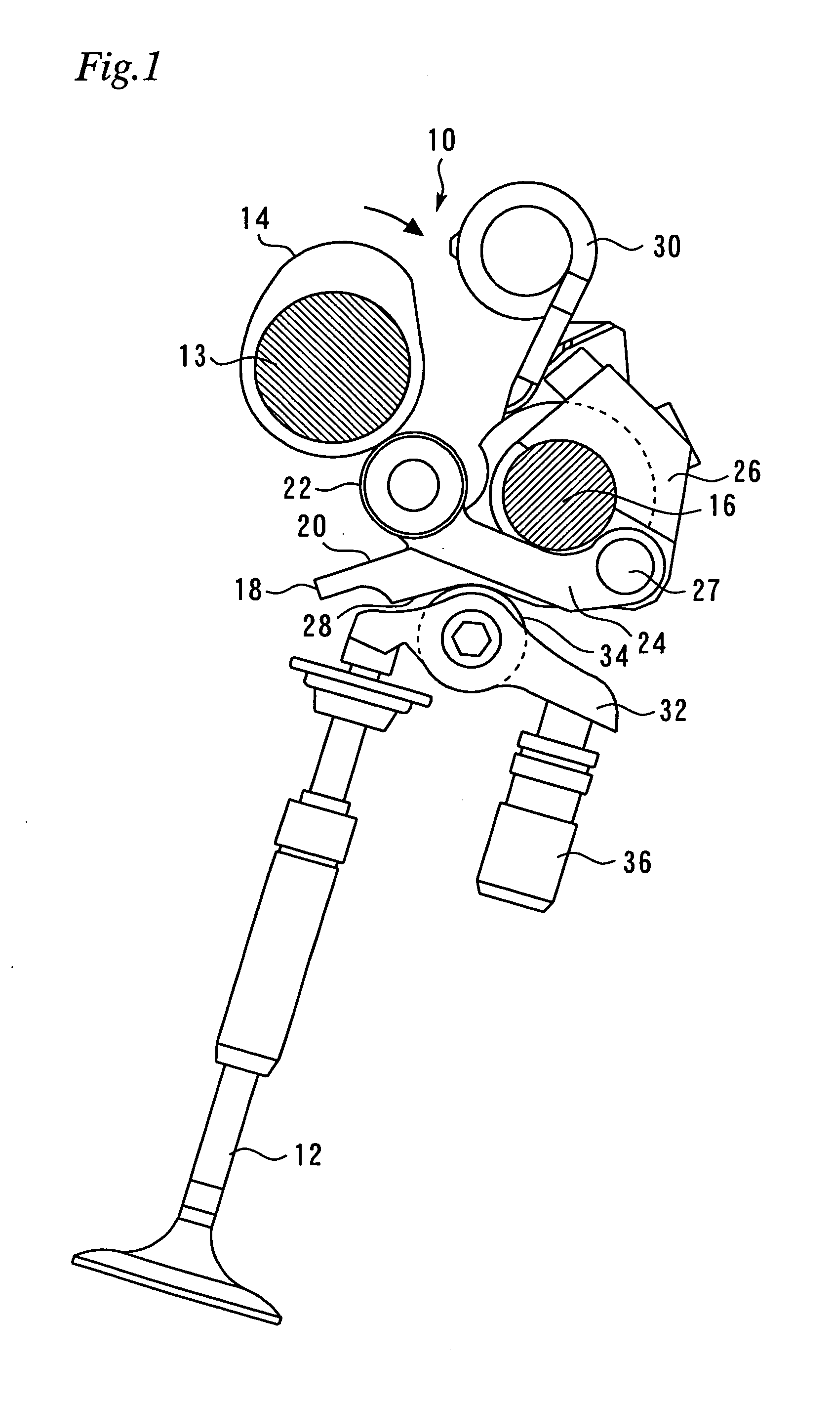
[0061]FIG. 1 is a side view illustrating a variable valve mechanism according to a first embodiment of the present invention. The following description assumes that the variable valve mechanism 10 shown in FIG. 1 drives an intake valve 12 of an internal combustion engine. However, the present invention can also be applied to a variable valve mechanism that drives an exhaust valve.
[0062]The variable valve mechanism 10 includes a cam 14, which is mounted on a camshaft 13. The camshaft 13 is rotationally driven by a crankshaft of the internal combustion engine. The cam 14 rotates clockwise as viewed in FIG. 1.
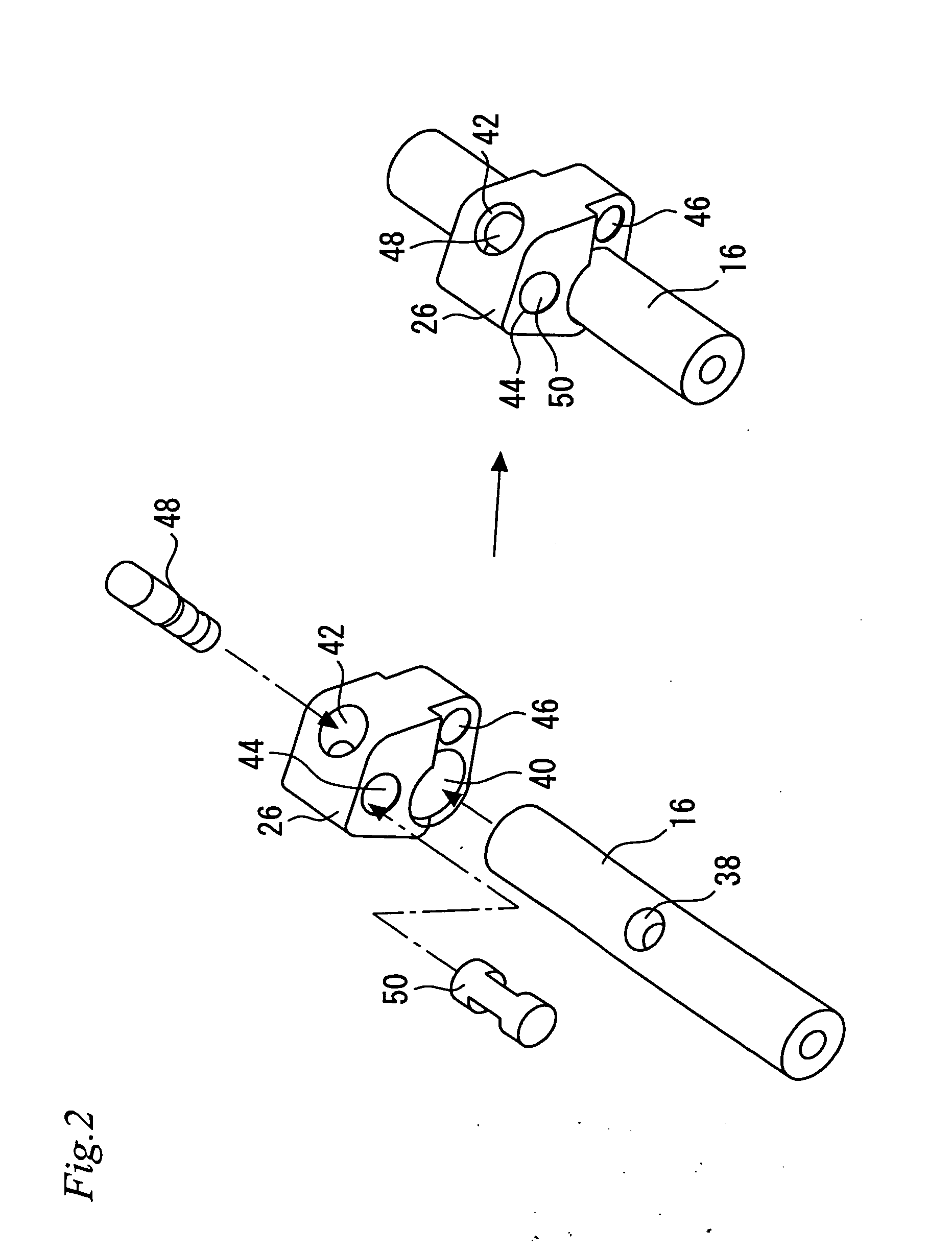
[0063]The variable valve mechanism 10 also includes a control shaft 16, which is positioned in parallel with the camshaft 13, and a control shaft drive mechanism (not shown), which can rotate the control shaft 16 within a predetermined angular range. The configuration of the control shaft drive mechanism is not specifically defined. However, the control shaft drive mechanism may b...
second embodiment
[0095]A second embodiment of the present invention will now be described with reference to FIGS. 5 and 6. However, the differences between the second embodiment and the above-described first embodiment will be mainly described while abridging or omitting the description of matters common to these embodiments.
[0096]FIG. 5 is a perspective view illustrating the control pin 48 according to the second embodiment. This control pin 48 has a protruding part 58, which is positioned between the contact face 52 between the control pin 48 and adjustment pin 50 and an insert 56 to be inserted into the pin insertion hole 38 in the control shaft 16.
[0097]FIG. 6 is a cross-sectional view of the assembled control shaft 16 and control member 26 according to the second embodiment taken in a plane perpendicular to the control shaft 16. In the present embodiment, the insert 56 of the control pin 48 and the pin insertion hole 38 are clearance fit. More specifically, the control pin 48 is not fastened to...
third embodiment
[0099]A third embodiment of the present invention will now be described with reference to FIGS. 7 to 9. However, the differences between the third embodiment and the above-described first embodiment will be mainly described while abridging or omitting the description of matters common to these embodiments.
[0100]FIG. 7 shows perspective views illustrating the exploded state and assembled state of the control shaft 16 and control member 26 according to the third embodiment. As shown in FIG. 7, a shim 60 is sandwiched between the control pin 48 and adjustment pin 50, and the control pin 48 and adjustment pin 50 are secured (coupled together) with a bolt 62. In addition, a nut 64 is provided to lock the bolt 62.
[0101]FIG. 8 is a cross-sectional view of the assembled control shaft 16 and control member 26 according to the third embodiment taken in a plane perpendicular to the control shaft 16. FIG. 9 is a cross-sectional view taken along line Y-Y of FIG. 8. As shown in FIGS. 8 and 9, the...
PUM
 Abstract
Description
Claims
Application Information