Hydraulic system having manifold with remote control for grain cart

a technology of hydraulic system and manifold, which is applied in the direction of transportation items, loading/unloading vehicle arrangment, refuse collection, etc., can solve the problems of hydraulic line exposure to possible damage, difficulty in hooking, etc., and achieve the effect of reducing the number of components and enhancing user safety and comfor

Inactive Publication Date: 2009-12-31
DETHMERS MFG
View PDF31 Cites 13 Cited by
  • Summary
  • Abstract
  • Description
  • Claims
  • Application Information

AI Technical Summary

Benefits of technology

[0010]The present invention has significant advantages over traditional devices. The remote control of the operations enhances user safety and comfort in control of the features of the grain cart as the user may hold the remote control in hand and simultaneously operate the control and view the operation of the device. Furthermore, only a single set of hydraulic lines are provided between the towing vehicle and the grain cart, providing ease of hook up and operation of the cart. Moreover, the central operation and control of the various functions of the grain cart stemming from a single position on the grain cart, and by use of a single controller, reduces the number of components in a hydraulic system and steps that must be taken by an operator to operate the moveable devices connected to the hydraulic system. Other advantages and features may become apparent from the following description, drawings, and claims.

Problems solved by technology

Unfortunately, the foregoing systems suffer several drawbacks.
As a result, a set of hydraulic lines for each functional component extend from the grain cart to the tractor, causing difficulty in hook-up and exposure of the hydraulic lines to possible damage.
Secondly, the hydraulic levers are commonly mounted such that the operator must turn away from the view of the grain cart to operate the control or turn away from the controls, making it difficult to monitor the position of the moveable components and creating an unsafe operating environment.
Third, the control levers are generally not labeled, so that an operator must use trial and error to determine the appropriate function he or she wishes to select.

Method used


Image

  • Hydraulic system having manifold with remote control for grain cart
  • Hydraulic system having manifold with remote control for grain cart
  • Hydraulic system having manifold with remote control for grain cart

Examples


Embodiment Construction

[0029]The invention is generally directed to an agricultural implement, and in particular a grain cart having a manifold hydraulically connected to a plurality of moveable components or devices on a grain cart.

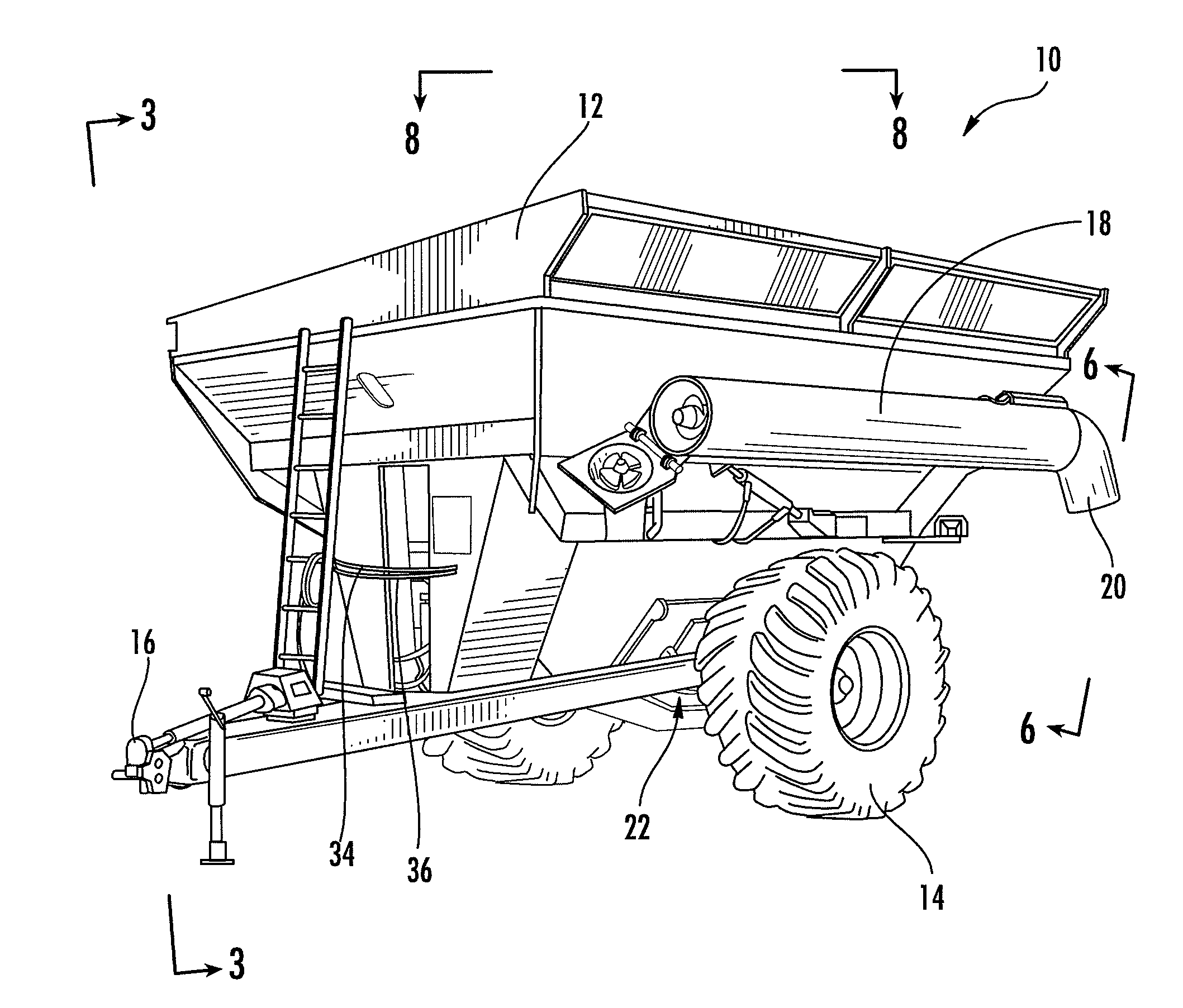
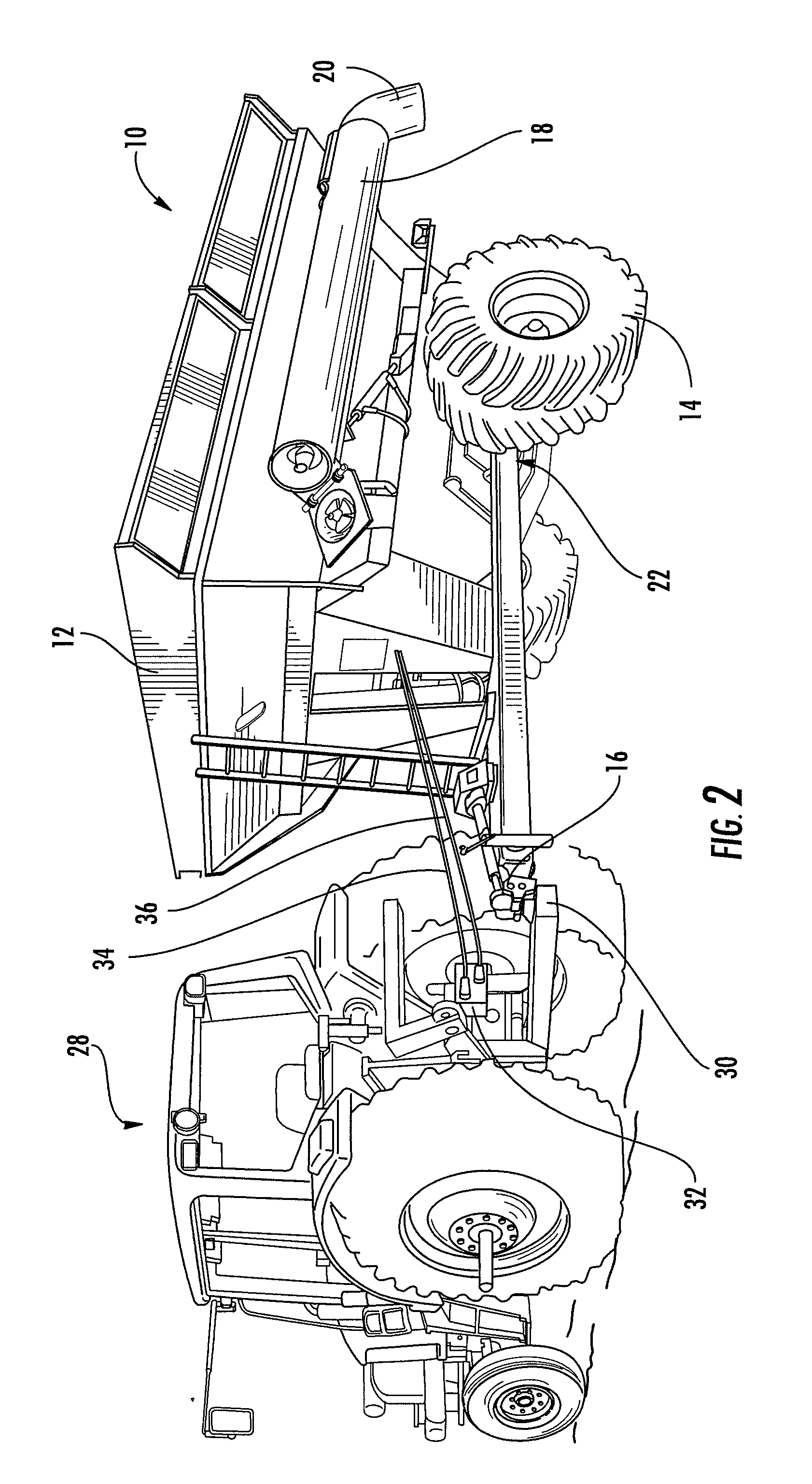
[0030]In an exemplary embodiment, the grain cart 10 includes a grain bin 12 for receipt and transport of grain or other material, one or more wheels 14 or track assemblies for movement and a hitch assembly 16. The grain cart 10 shown in FIG. 1 also includes a foldable auger 18, a rotatable chute 20, and a grain bin door 22 (best seen in FIG. 8) each of which may be hydraulically controlled. While an auger 18, chute 20 and door 22 are specifically discussed it is understood that additional hydraulically controlled components or devices may be provided in addition to or in place of the exemplary devices described.

[0031]Referring generally to FIGS. 1-5, the grain cart 10 may further include a hydraulic control assembly 24, including a manifold 26, one or more hydraulic lines or h...


PUM


Abstract

A grain cart is provided having a plurality of moveable devices positioned thereon which are hydraulically controlled. A manifold is mounted to the grain cart and hydraulically connected to more than one of the plurality of moveable devices. A remote control is provided in communication with the manifold to hydraulically control movement of the moveable devices hydraulically connected to the manifold. A remote control for controlling functions of a grain cart and a method of assembling of a control assembly are also disclosed.

Description

SCOPE OF THE INVENTION[0001]The present invention relates to agricultural implements, and in particular, the control of hydraulic components of a grain cart.BACKGROUND[0002]Agricultural implements, and in particular grain carts are known and generally include one or more hydraulically operated or controlled components.[0003]Hydraulic systems are often used on such grain carts or agricultural implements to control moveable components or parts, particularly where a large load must be overcome. Generally, hydraulic systems include oil that may flow and transmit power. Hydraulic oil or fluid is typically contained in a reservoir mounted to the implement or device. Hoses are used to direct the hydraulic fluid to the appropriate locations, and typically include low pressure hoses, high pressure hoses or lines, and rigid style hoses. From the reservoir the hydraulic fluid flows through a low-pressure hose to a pump which may be powered by a number of sources. For example, a tractor will of...

Claims


Application Information

Patent Timeline
Patent Type & Authority Applications(United States)
IPC IPC(8): B60K25/00B60P1/40
CPCB60P1/42F15B13/0857F15B13/0835F15B13/0814
Inventor JOHNSON, MICHAEL R.
Owner DETHMERS MFG
Why Eureka
Try Eureka