
Filtration Module

a technology of filtration module and module, which is applied in the direction of filtration separation, membranes, separation processes, etc., can solve the problems of less connection to process equipment, less free liquid remaining in the module, and defect of particles deposited on semiconductor wafers

Active Publication Date: 2009-12-31
ENTEGRIS INC
View PDF21 Cites 26 Cited by
  • Summary
  • Abstract
  • Description
  • Claims
  • Application Information

AI Technical Summary

Benefits of technology

[0009]Accordingly, it would be desirable to provide a filtration module construction having a plurality of filtration cartridges which avoids the need for applying force in a plurality of directions of movement to effect removal of a plurality of cartridges from a manifold. Such a filtration module would provide an increased filter surface area per unit volume of filtration module as compared to a filtration module having a single cartridge. Such a construction would also promote ease of separating the cartridge from the manifold and would eliminate the danger to the worker in removing the filtration cartridge subsequent to filtration.SUMMARY OF THE INVENTION
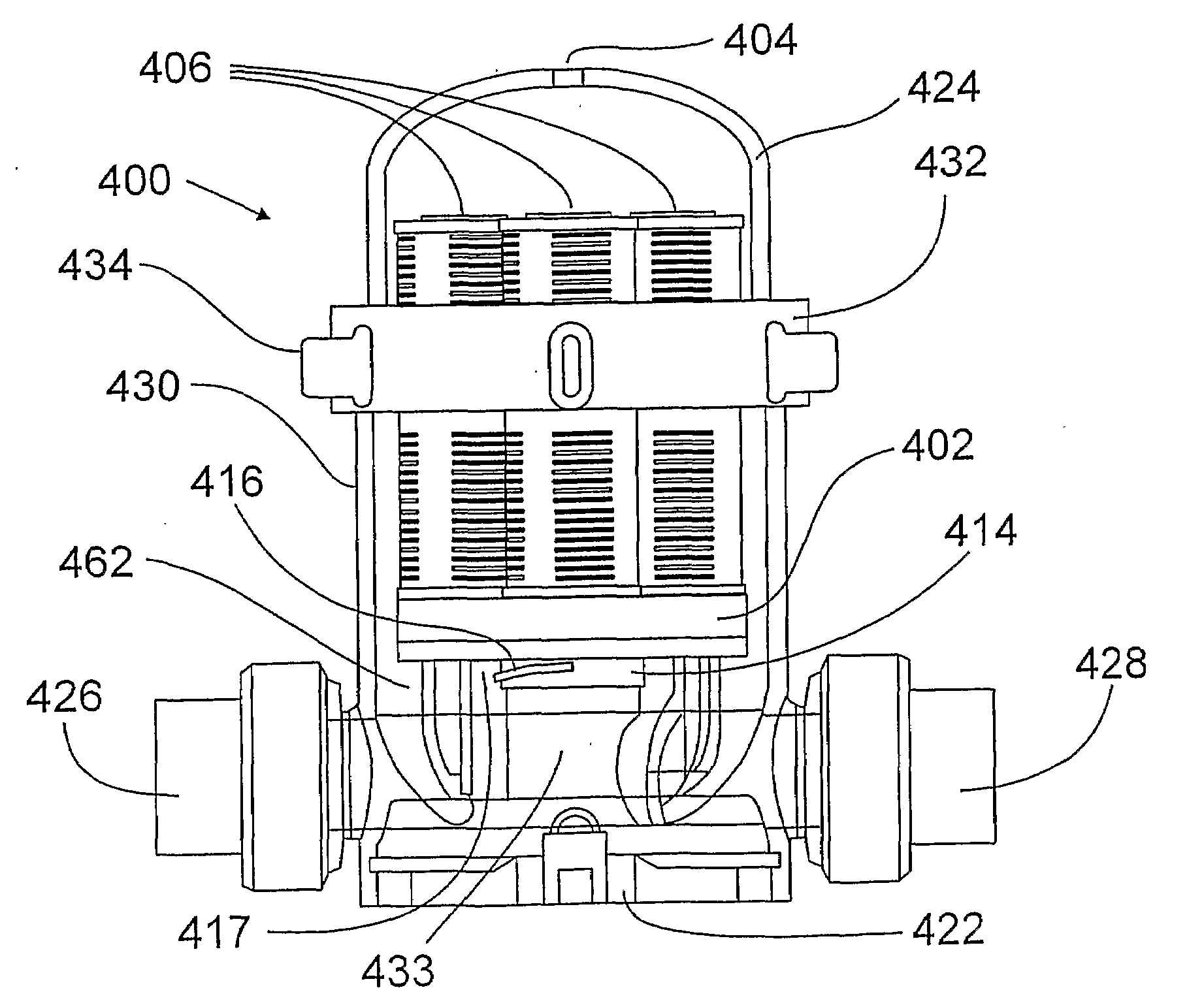
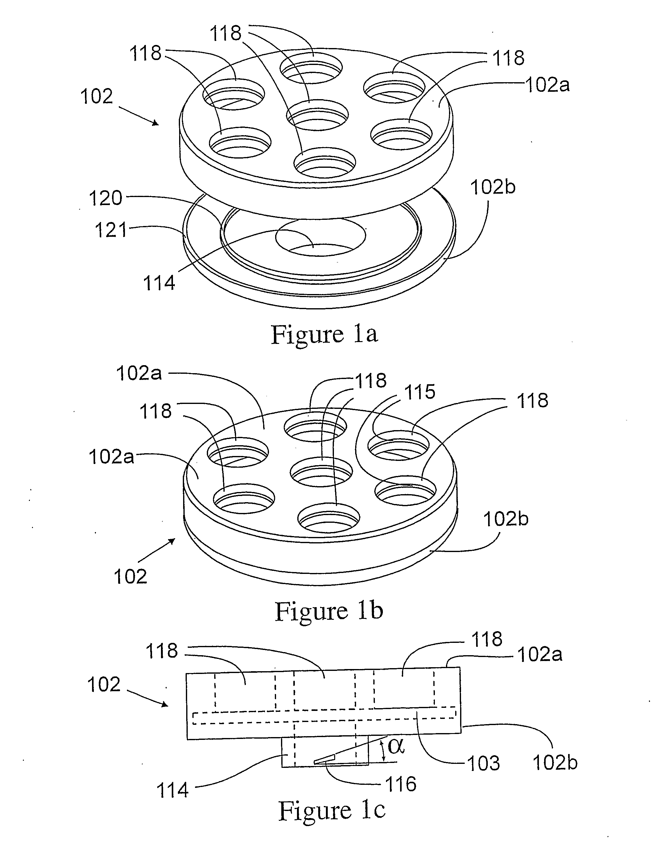
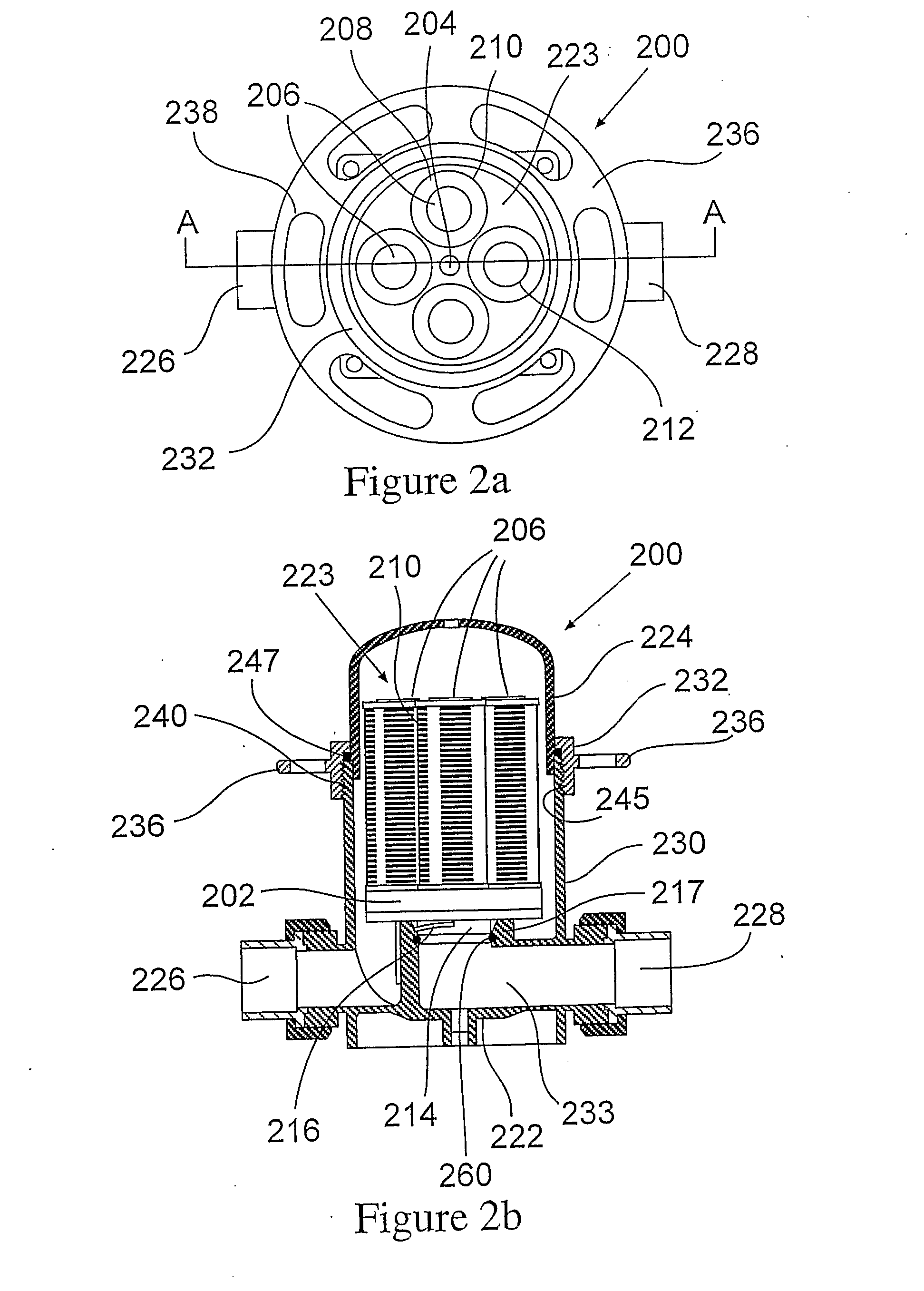
[0010]Embodiments of the present invention include an apparatus that can comprise a manifold and a bowl or cap joined together in a fluid tight manner. The cap and manifold house a porous purification membrane that is mounted, joined or otherwise connected to the support. The porous purification membrane may be used to remove particulate, molecular, ionic, or combination of these contaminants from a liquid. The support has membrane supporting portion and a support outlet. The support outlet fits inside of an outlet conduit of the manifold and the support outlet can have two or more angled structures that engage with angled mating structures of the outlet conduit of the manifold with less than a full turn. In some embodiments the support outlet and manifold engage with a turn of about 90 degrees or less. The support outlet and manifold engage to form a fluid tight seal between the support outlet and outlet conduit of the manifold. The porous purification membrane and bowl are in fluid communication with the manifold in a manner which prevents mixing of a fluid or liquid feed to the apparatus and the filtered permeate and or purified liquid removed from the apparatus.
[0019]The high flow purification and or filtration apparatus can be made from chemically resistant materials. In some embodiments it can be made from polymeric materials or composites of polymers and other materials such as ceramics, fibers, or other fillers. In some embodiments the apparatus is metal free. The engagement of the partially angled structure on the support outlet and manifold outlet eliminates the need for tie rods or pipes, positioning guides inserted into the filter or purifier core which can cause contamination of treated liquid. The engagement of the partially angled structure on the support outlet and manifold outlet eliminates the need for base and header plates, springs and other structures which make assembly and disassembly of filtration modules difficult and time consuming and can reduce fluid flow or create dead spots for flow in the housing. Embodiments of the invention can have a single seal for the purification cartridge at the outlet rather than having inlet and outlet seals. This invention relates to a membrane purification module that is more sanitary and is easier to replace and install than presently available filtration and or purification modules. In some embodiments of the present invention, the purification media is a membrane filtration module formed from a filtration cartridge, a retaining bowl and a manifold joined together. In other embodiments the purification media is a membrane filtration module having a support for a plurality of filtration cartridges; the membrane filtration module formed from a plurality of filtration cartridges, a support for the filtration cartridges, a retaining bowl and a manifold joined together.

Problems solved by technology

It is well known that any particle that is deposited on a semiconductor wafer produces a defect when the particle is sufficiently large.
First, they are more difficult to connect to the process equipment since the module is sandwiched between two sets of connections.
Second, any free liquid remaining within the module quickly drains upon disconnection of the module because at least one connection is positioned at the bottom of the module.
This, in turn, requires application of considerable force on the cartridge when effecting its removal from the bowl that may require the use of a hand held tool.
The application of a rotational force and a lifting force as a single motion increases the difficulty of separating the bowl from the filter cartridge.
Separation of the cartridge from the bowl is particularly difficult when toxic or corrosive fluids have been filtered by this filtration device.
Any application of back pressure when applied to the cartridge can cause the cartridge to unseat from the manifold, rendering it ineffective for filtration.

Method used


Image

  • Filtration Module
  • Filtration Module
  • Filtration Module

Examples


Embodiment Construction

[0042]Embodiments of the present invention include an apparatus that can comprise a manifold that is in fluid communication with an outlet from a membrane purification media, and a bowl or cap connected to the manifold. The bowl and manifold enclose the membrane purification media. In versions of the invention both the manifold and bowl can be polymeric materials or composite materials that include polymers. The bowl or cap and a section of the manifold are joined in a fluid tight manner, the seal can be reversibly made and broken by press fit, or compression of a polymeric sealing material such as one or more gaskets, o-rings, joint tape, or other materials. The seal between the bowl or cap and the manifold section may be and held by nuts and bolts, clamps, retaining ring, or other seal maintaining structures. In some embodiments the bowl is joined to a cylindrical section of the manifold. The height of the manifold section and bowl or cap may be varied to house the purification me...


PUM

PropertyMeasurementUnit
angleaaaaaaaaaa
angleaaaaaaaaaa
angleaaaaaaaaaa

Abstract

A purification module is provided comprising a plurality of purification cartridges, a support for the cartridges, a manifold and a bowl. In one embodiment the support for the cartridges has two pitched partial screw threads on opposing surfaces which mate with pitched screw flights on the manifold when the partial screw threads are rotated into the screw flights. The support includes fluid passageways for directing filtered fluid from the filtration cartridges, through the support and into the manifold. In another embodiment, a purification module is provided comprising a purification cartridge, a manifold and a bowl. The purification cartridge has two pitched partial screw threads on opposing surfaces of the cartridge outlet which mate with screw flights on the manifold when the partial screw threads are rotated into the mating screw flights.

Description

[0001]This application claims priority to Japanese Patent Application No. 2005-201780, filed Jul. 11, 2005, and priority to U.S. Provisional Application No. 60 / 698,267 filed Jul. 11, 2005, the contents of each of these applications incorporated herein by reference in their entirety.[0002]The control of particulate contaminants in a filtration process such as in the semiconductor industry requires the use of ultraclean filters having membranes that remove submicron particles. It is well known that any particle that is deposited on a semiconductor wafer produces a defect when the particle is sufficiently large. Typically in the semiconductor industry, failed defects can be produced by particles as small as about one tenth of the smallest features of the semiconductor chip. Therefore, membrane filters are used in numerous process steps for producing semiconductor chips to purify both working liquids and gases.[0003]Although many different designs have been developed for a filtration mo...

Claims


Application Information

Patent Timeline
Patent Type & Authority Applications(United States)
IPC IPC(8): B01D29/13
CPCB01D29/21B01D2313/44B01D2201/0407B01D2201/0415B01D2201/0453B01D2201/24B01D2201/291B01D2201/4015B01D63/067B01D2313/20B01D2313/105B01D2313/04B01D29/52B01D29/96B01D2313/041B01D2313/2031B01D29/13B01D63/14
Inventor SUZUKI, YASUJIMCNAMARA, ERICTOWLE, TIMOTHY
Owner ENTEGRIS INC
Learn More