Notch antenna having a low profile stripline feed

a low-profile, antenna-type technology, applied in the direction of stripline fed arrays, instruments, using reradiation, etc., can solve the problem of inpractical layered connection

Active Publication Date: 2009-12-31
MASSACHUSETTS INST OF TECH
View PDF16 Cites 43 Cited by
  • Summary
  • Abstract
  • Description
  • Claims
  • Application Information

AI Technical Summary

Problems solved by technology

Conventional notch antennas require a feed that extends away from the antenna element so that layered connections are not practical.

Method used


Image

  • Notch antenna having a low profile stripline feed
  • Notch antenna having a low profile stripline feed
  • Notch antenna having a low profile stripline feed

Examples


Embodiment Construction

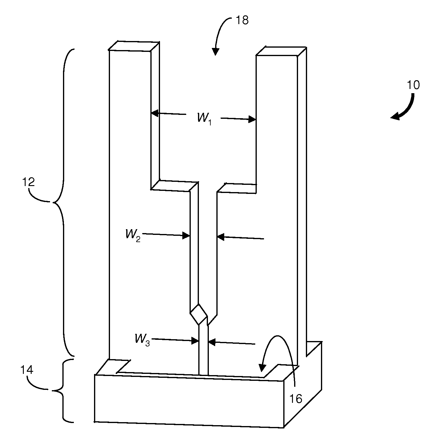
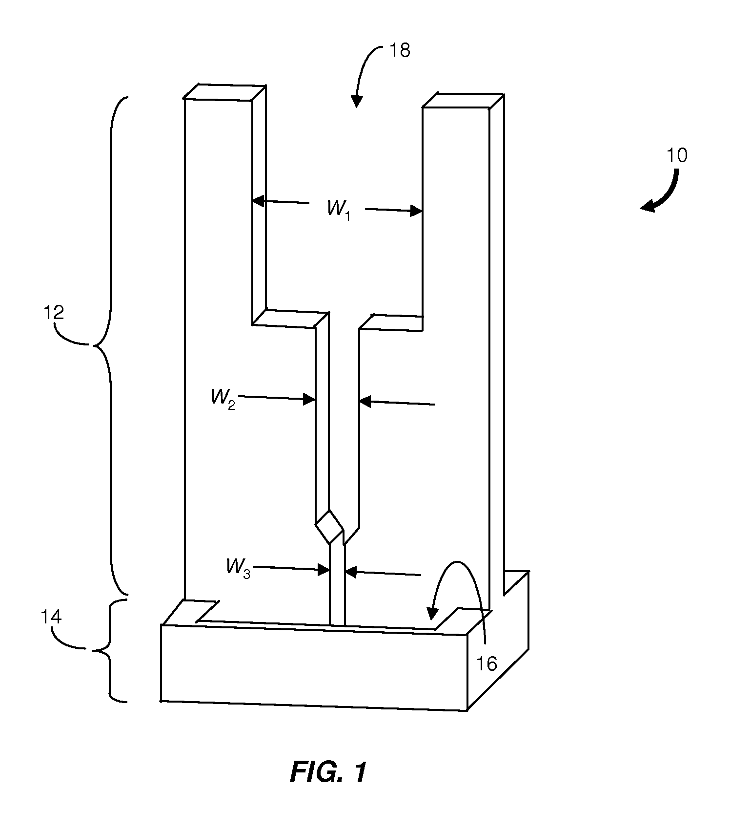
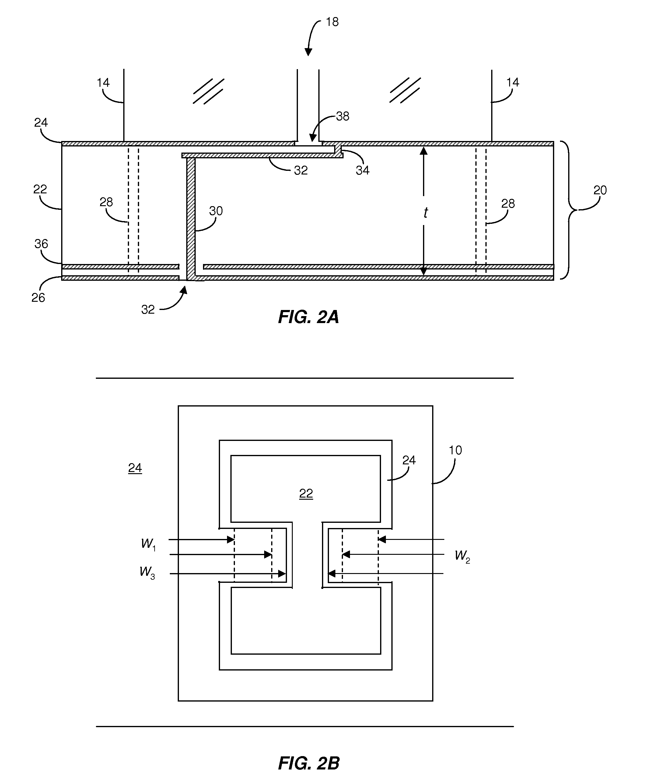
[0014]The invention relates to a notch antenna having a low profile stripline feed. Notch antenna elements fabricated from solid conductor materials and mounted on a printed circuit board (PCB) according to the invention provide superior heat dissipation when compared to conventional ESA antennas having vertical feeds. Thermally conductive vias (i.e., “thermal vias) extending between the metallized surfaces of the PCB conduct heat generated by components surface mounted to the opposite side of the PCB from the notch antenna elements. Excess heat is removed by airflow passing over the antenna elements. Moreover, system components and electrical routing can be fabricated in a single PCB structure. In contrast, conventional ESA antennas require mechanical connectors to couple the RF signals to or from each antenna element to other structures where the RF signals are distributed or processed. Consequently, the total volume and weight of the ESA antenna of the invention is substantially ...


PUM


Abstract

Described are a notch antenna and an array antenna based on a low profile stripline feed. The notch antenna includes a planar dielectric substrate having upper and lower surfaces. Each surface has a conductive layer with an opening therein. A notch antenna element is disposed on the conductive layer of the upper surface at the opening. A stripline embedded in the planar dielectric substrate extends under the notch antenna element. The stripline is adapted to couple an RF signal between the stripline and the notch antenna element. A conductive via is electrically coupled to the stripline and extends from the stripline to the opening in the conductive layer on the lower surface so that the RF signal is accessible at the lower surface.

Description

RELATED APPLICATION[0001]This application claims the benefit of the earlier filing date of U.S. Provisional Patent Application Ser. No. 60 / 940,739, filed May 30, 2007, titled “Ultra-Wideband Step Notch Array Using Stripline Feed,” the entirety of which is incorporated herein by reference.GOVERNMENT RIGHTS IN THE INVENTION[0002]This invention was made with U.S. Government support under Contract No. FA8721-05-C-0002, awarded by the United States Air Force. The government may have certain rights in the invention.FIELD OF THE INVENTION[0003]The present invention relates generally to electronically scanned array (ESA) antennas. More particularly, the invention relates to a notch antenna element having a low profile stripline feed.BACKGROUND OF THE INVENTION[0004]ESA antennas are used for a wide range of applications including cellular telephone networks, telemetry systems and automotive, shipboard and airborne radar systems. ESA antennas capable of efficiently radiating over wide bandwid...

Claims


Application Information

Patent Timeline
Patent Type & Authority Applications(United States)
IPC IPC(8): H01Q13/10H01Q21/00
CPCH01Q13/106H01Q21/064H01Q21/0081H01Q21/0025
Inventor BRIGHAM, GLENN A.DAVIDOVITZ, MARATDUFFY, SEAN M.HERD, JEFFREYDAVIDOVITZ, ZHANNA
Owner MASSACHUSETTS INST OF TECH
Why Eureka
Try Eureka