ECG electrode and electrode support

a technology applied in the field of electrodes and supports, can solve problems such as quality degradation, and achieve the effect of easy attachmen

Active Publication Date: 2009-12-31
PHYSIO CONTROL INC
View PDF7 Cites 18 Cited by
  • Summary
  • Abstract
  • Description
  • Claims
  • Application Information

AI Technical Summary

Benefits of technology

[0007]It is an object of the present invention to provide an ECG electrode for use in apparatus for treating sudden cardiac arrest in a patient by compression of the sternum, which is easily attached to the skin of the patient's back.
[0017]According to a fifth preferred aspect of the invention the ECG electrode comprises an electrically conductive electrode disk, a resiliently compressible spring means disposed between the electrode disk and the support, and a flexible conducting means for connecting the electrode disk to an ECG monitoring unit. This arrangement minimizes disturbances of the ECG signal by body geometry changes caused by the compression of the sternum. The electrode of the invention is freely movable in the recess in a direction perpendicular to the support while its lateral movement is rather restricted. By the force of a spring means the front face of the electrode is pressed against the skin of the patient's back to provide good electrical contact. Its front face may be provided with electrical contact enhancing means, such as with an electrically conducting gel or paste known in the art.
[0019]The recess for mounting of the electrode of the invention on the support is disposed on an essentially flat face thereof and has a form preferably allowing the electrode to be fully inserted into the recess against the resilient force of the spring means which, with their one end, abut the bottom of the recess. It is preferred that, in a non-load bearing state, the electrode disk extends from the recess for a short distance. It is preferred for the circumference of the recess and of the electrode disk, the support element, and the combination of electrode disk and support element to be of similar form and diameter similar so as to provide guidance by the side walls of the recess for the movement of the electrode with little play.

Problems solved by technology

The ECG signals obtainable in this manner are however strongly affected by the movement of sternum during compression, which impairs their quality.

Method used


Image

  • ECG electrode and electrode support
  • ECG electrode and electrode support
  • ECG electrode and electrode support

Examples


Embodiment Construction

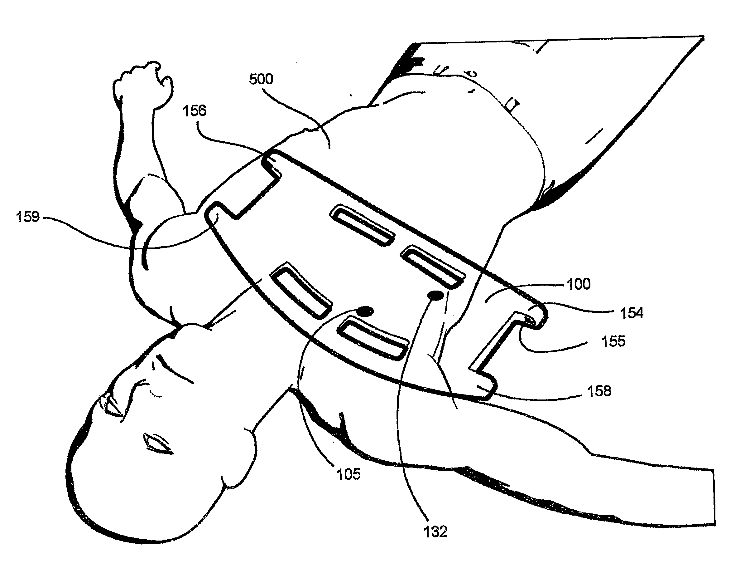
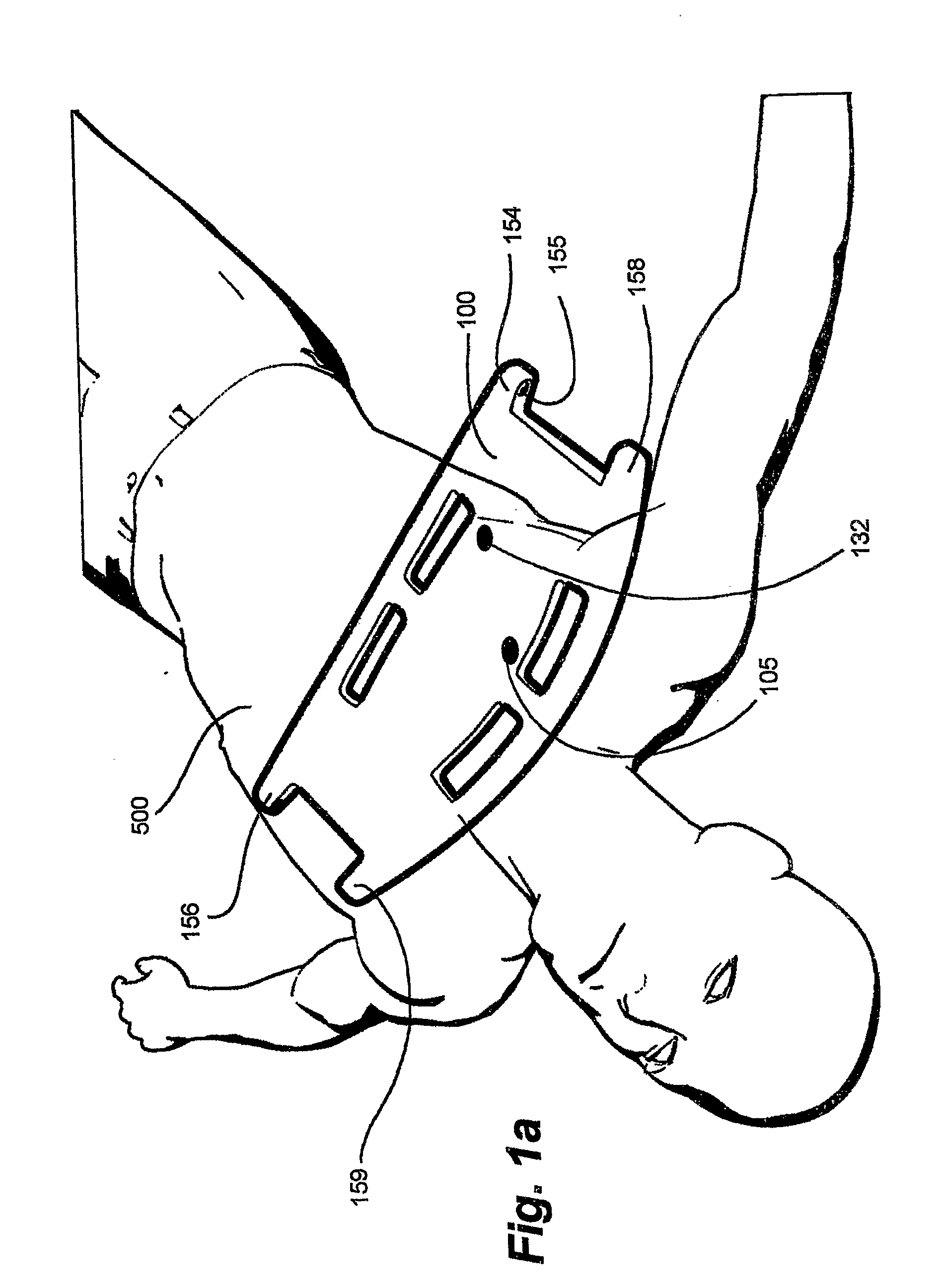
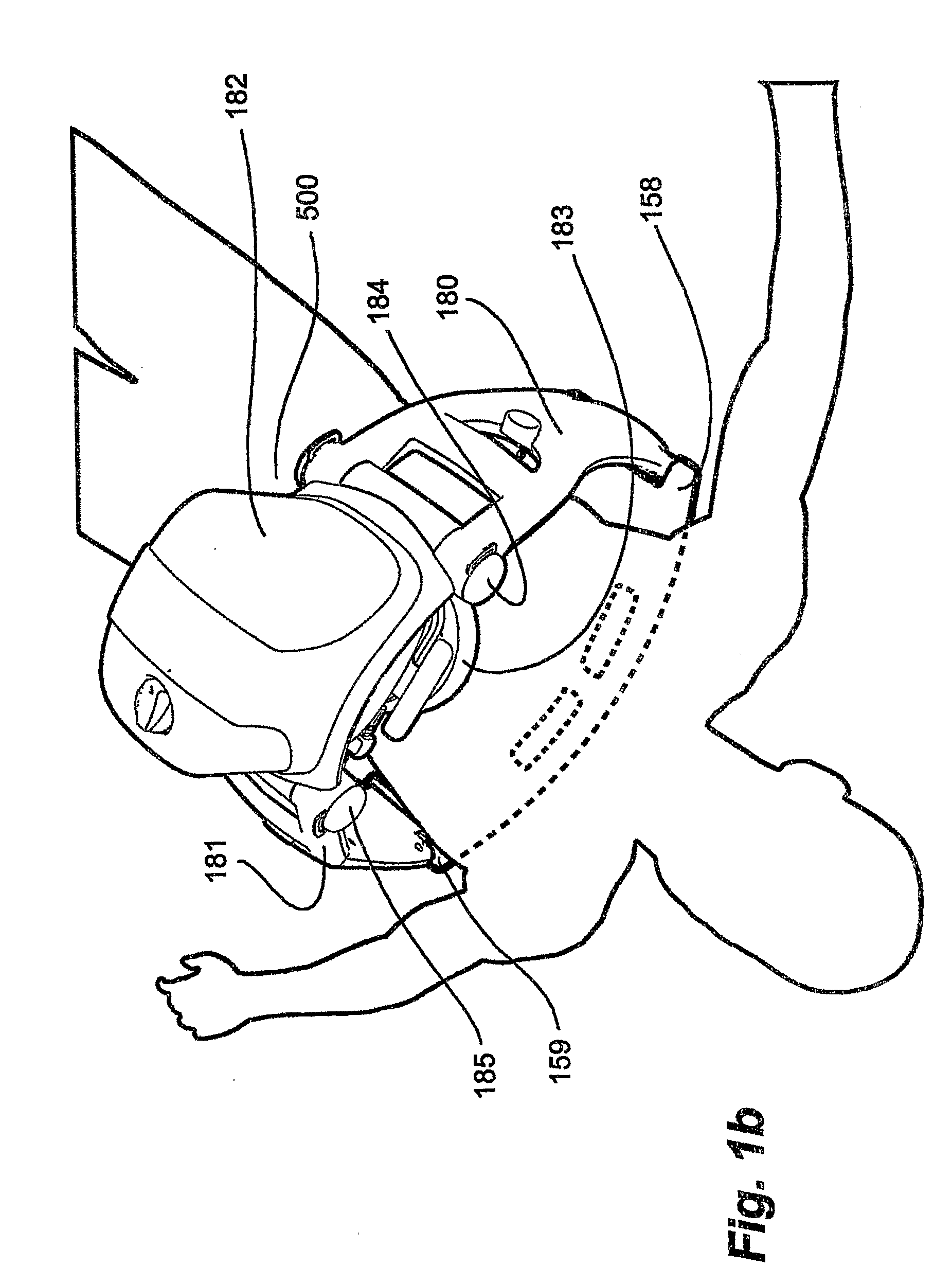
[0032]FIG. 1a shows a seemingly lifeless patient in a supine position, the trunk 500 of whom has been placed on a back plate 100 resting on a floor. All clothing on the trunk has been removed in preparation for resuscitation by a central unit 182 (FIG. 1b) for compression of the sternum. In FIG. 1b the remainder of the apparatus is shown in a state mounted to the back plate 100. Mounting is accomplished in the following manner: the free ends of curved right 180 and left 181 legs swivelingly attached by means of joints 184 and 185, respectively, to the central pneumatic compression unit 182 from which a reciprocating plunger ending in a suction cup 183 extends towards the sternum of the patient are mounted in lateral brackets 154; 158 and 156; 159 of the back plate 100 provided with bores 155 for releasable insertion of short shafts (not shown) extending from said free ends. Left” and “right” designate positions from the patient's perspective. The apparatus, which shares the general ...


PUM


Abstract

An electrically non-conductive back plate for supporting the back of a patient in a supine position comprises on its front face facing the back of the patient a pair or more of ECG electrodes capable of maintaining electrically conductive skin contact with the patient's back. The pair of ECG electrodes is disposed at a sharp angle with the mean heart vector, in particular so as to form an angle β of about 45°±25° with the projection S of the patient's spine on the back plate. Also disclosed is an ECG electrode for mounting in a recess of the back plate and an apparatus for treating cardiac arrest by compression of the sternum comprising the back plate.

Description

FIELD OF THE INVENTION[0001]The present invention relates to an ECG electrode and a support on which the ECG electrode is mounted, in particular for use in apparatus for treating sudden cardiac arrest.BACKGROUND OF THE INVENTION[0002]Sudden cardiac arrest is commonly treated mechanically and / or by electrical defibrillation. Mechanical treatment may be given manually or by a chest compression apparatus. A number of chest compression apparatus are known in the art, such as the pneumatically driven LUCAS™ mechanical chest compression system (“Lucas™ system”; an apparatus for compression and physiological in Cardio-Pulmonary Resuscitation, CPR, manufactured by Jolife AB, Lund, Sweden). Specifically the Lucas™ system comprises a support structure and a compression unit. The support structure includes a back plate for positioning the patient's back posterior to the patient's heart and a front part for positioning around the patient's chest anterior to the heart. The front part has two leg...

Claims


Application Information

Patent Timeline
Patent Type & Authority Applications(United States)
IPC IPC(8): A61B5/0402A61B5/25A61B5/282
CPCA61B5/04085A61B5/68A61B5/683A61B2560/0412A61B5/0408A61H31/006A61H31/008A61H2230/06A61H31/004A61B5/282A61B5/251
Inventor HULDT, OLOF
Owner PHYSIO CONTROL INC
Why Eureka
Try Eureka