
Rail system for a powered pallet conveyor

Inactive Publication Date: 2010-01-07
ROFA ROSENHEIMER FORDERANLAGEN
View PDF13 Cites 17 Cited by
  • Summary
  • Abstract
  • Description
  • Claims
  • Application Information

AI Technical Summary

Benefits of technology

[0009]It is the problem of the present invention to provide a rail system for a powered pallet conveyor which allows the vehicle to travel continuously across the switching means without stopping while the switching means has reduced space requirements and does not subject vehicles to acceleration / deceleration during switching so that wear is reduced and early failure of the vehicle and high maintenance costs are avoided.

Problems solved by technology

Both switch means are unsatisfactory in that the vehicle cannot travel continuously across the switching means without stopping.
As a consequence, the presence of a switching means results in a limitation of the maximum speed by which the powered pallet conveyor is capable of completing a task.
Limitations imposed by the switching means are even greater in cases when more than one switching is required per travel of the powered pallet conveyor.
Furthermore, conventional switching means have significant space requirements.
Moreover, vehicles subjected to frequent acceleration / deceleration suffer from increased wear and earlier failure so that maintenance costs are high.

Method used


Image

  • Rail system for a powered pallet conveyor
  • Rail system for a powered pallet conveyor
  • Rail system for a powered pallet conveyor

Examples


Embodiment Construction

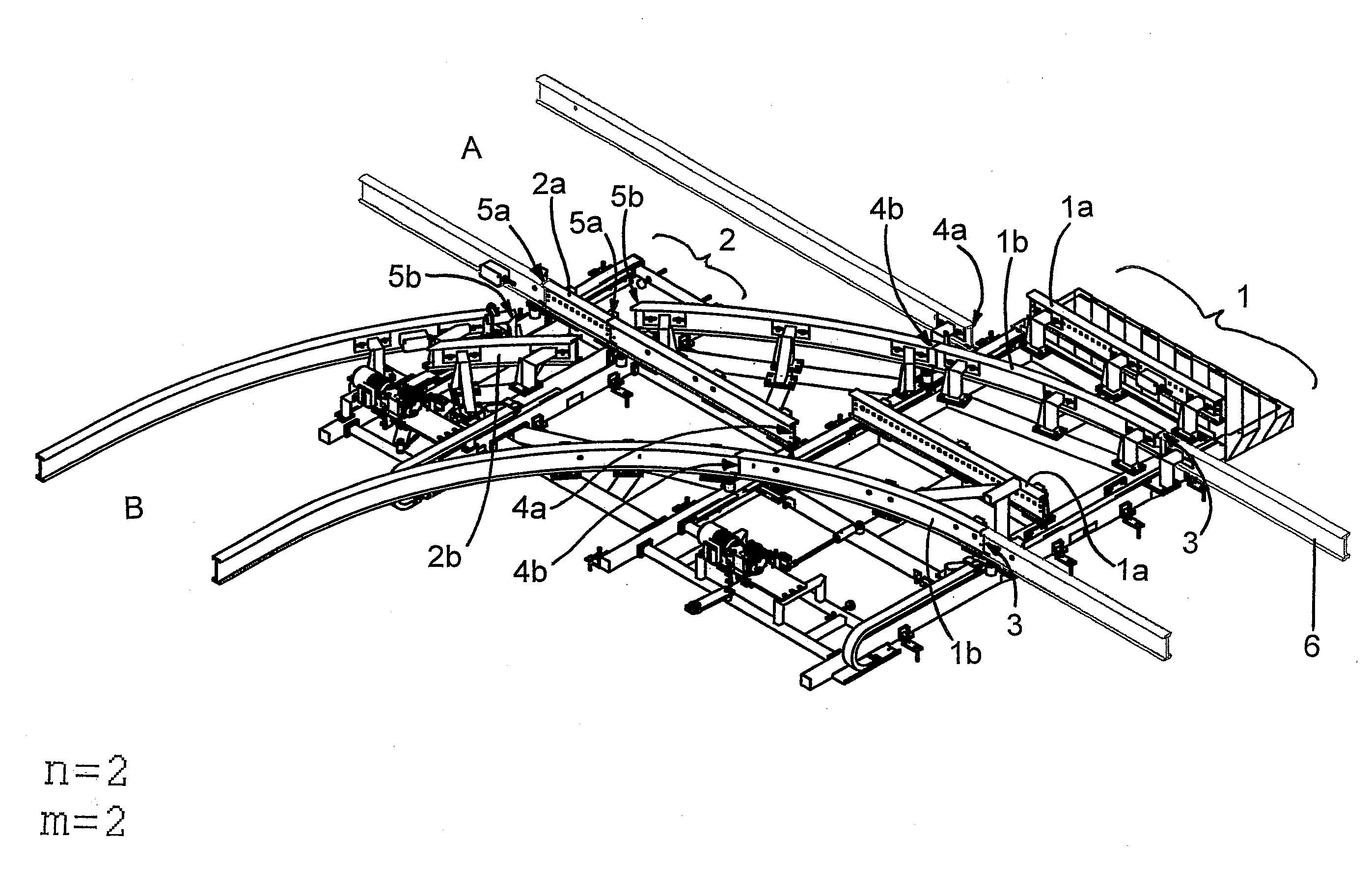
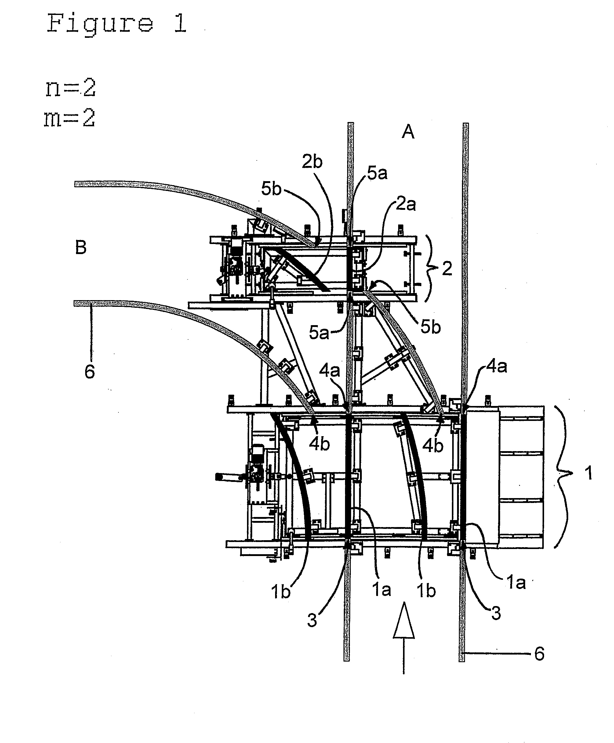
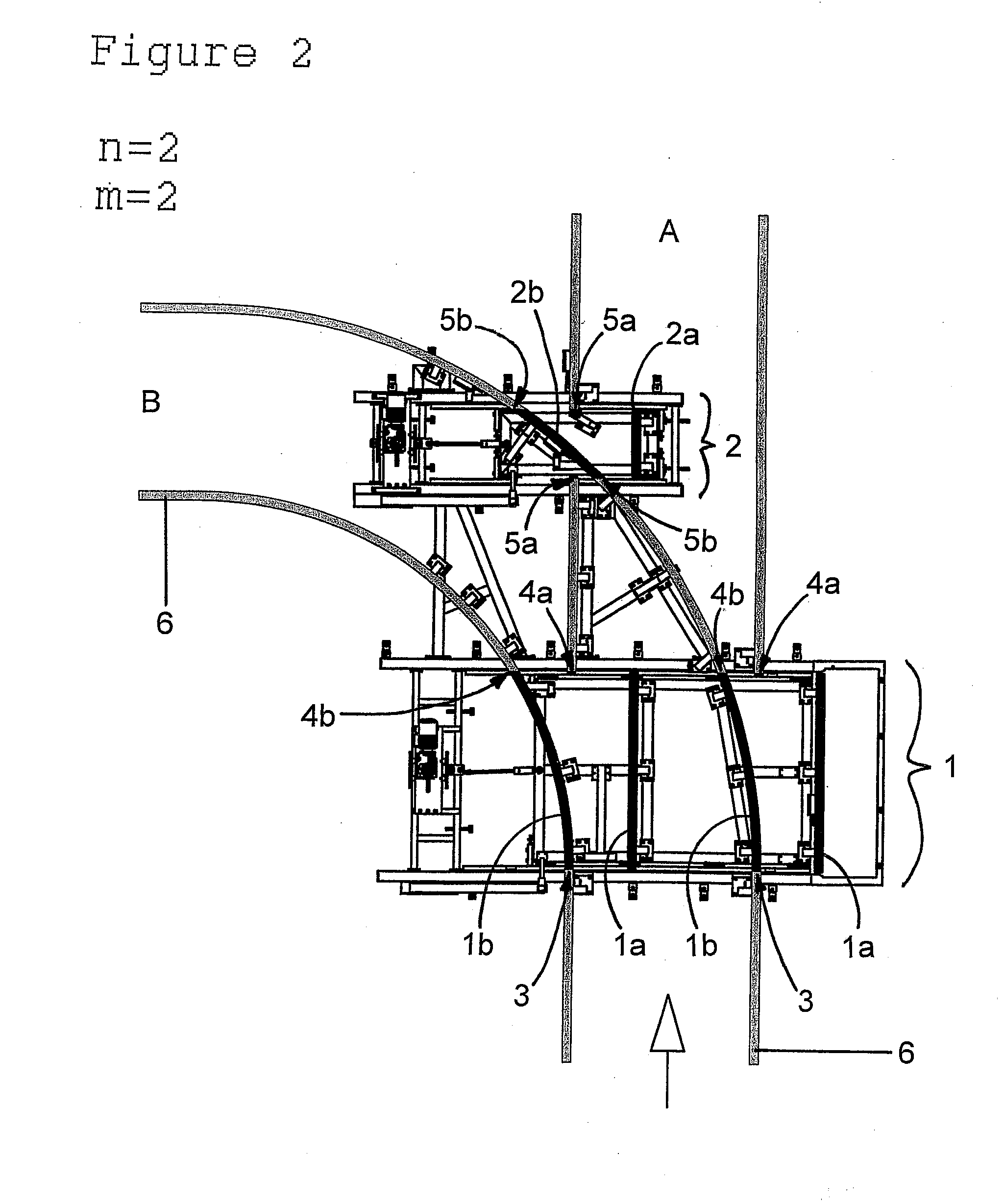
[0028]The present invention relates to a rail system for a powered pallet conveyor. The rail system comprises alternative pathways for a vehicle conveying a pallet along rails. A pathway in general means a connection between a starting point of a vehicle and a destination point of the vehicle which is provided by rails.

[0029]The powered pallet conveyor vehicle may be either loaded with a pallet or not. The vehicle conveys a pallet, either loaded or empty, on a pathway of the rail system. The pallet may be conveyed along the rail system with reduced frictional resistance by the use of wheels. The wheels may be attached to the vehicle by means of a bogey or bearing system and / or to the rails, so that they function as rollers or skatewheels. The wheels additionally serve to guide the vehicle along the rails and / or effect conveyance of the pallet.

[0030]The vehicle is powered by electrical potential energy, wherein an electric motor or motors convert the potential energy into movement of...


PUM


Abstract

A rail system for a powered pallet conveyor, which comprises alternative pathways having an electric cable provided on at least one of n parallel rails defining a travel pathway, wherein n≧2, whereby the rail system includes a switch for switching between m alternative travel pathways, wherein m≧2, and allowing the vehicle to continuously move across the switch after switching, said switch comprising a first actuator for selectively positioning (m*n) rigid rail portions bridging the distance between rail ends at (i) n joining points where the n parallel rails of each of the m alternative travel pathways subject to switching converge, and (ii) (m*n) continuation points where each alternative pathway subject to switching diverges downstream from the joining points. A second actuator selectively positions [m(n−1)] rigid rail portions bridging the distance between rail ends, where each alternative pathway is discontinued downstream from the corresponding continuation points.

Description

CROSS-REFERENCE TO RELATED APPLICATION[0001]This application claims priority to European Patent Application No. EP 08 012 241.9, filed Jul. 7, 2008, the contents of which are incorporated by reference herein in its entirety.FIELD OF THE INVENTION[0002]The present invention provides a rail system for a powered pallet conveyor. Moreover, the present invention provides a process for operating a switch of a rail system for a powered pallet conveyor. The present invention uses a switch means for switching between m alternative travel pathways, wherein m≧2, and allowing the vehicle to continuously move across the switch after switching.BACKGROUND OF THE INVENTION[0003]Powered pallet conveyors are known. Powered pallet conveyors may be used for loading or unloading trucks and trailers with product on pallets or in containers. Powered pallet conveyors may comprise a vehicle and a rail system which defines pathways on which the vehicle may travel.[0004]Conventional rail systems for a powered...

Claims


Application Information

Patent Timeline
IPC IPC(8): E01B25/15
CPCE01B23/06E01B7/00B61B13/00B65G35/06E01B25/26
Inventor MEINZINGER, BRUNO
Owner ROFA ROSENHEIMER FORDERANLAGEN
Learn More