Solar array support methods and systems

a solar array and support method technology, applied in the field of solar energy capture, can solve the problems of difficult and expensive implementation of solar panel arrays in remote locations, difficult and expensive solar panel array installation in environmentally sensitive areas without significantly affecting the surrounding habitat, etc., and achieves the effects of easy integration, easy construction and increased surface area

Inactive Publication Date: 2010-01-07
P4P HLDG
View PDF115 Cites 39 Cited by
  • Summary
  • Abstract
  • Description
  • Claims
  • Application Information

AI Technical Summary

Benefits of technology

[0018]In yet another aspect of the present invention, the type and arrangement of the pods / receivers and the types of PV cells are selected based upon the particular intended use of the invention, such as whether the invention is intended solely for producing power, or to also achieve a secondary function such as providing shade, serving as a structure with a roof, and others. For example, the solar panels can be conventional planar solar panels that are mounted on the receivers / pods in a desired arrangement. In another example, the solar panels may include cylindrical shaped PV cells such as those manufactured by Solyndra™ of Fremont Calif. As mentioned, one advantage of tubular / cylindrical shaped PV elements is that they provide an increased surface area for the photoaltaic cells as compared to planar arranged PV cells, and the tube shaped cells are self-tracking in that a portion of the outer surface of the tubes can be more easily oriented in a direct relationship with sunlight as sunlight angles change during the course of a day.
[0019]Because of the many different arrangements of solar panels that can be produced with the cable and column combinations, the present invention has the capability to be employed in many different land uses. The systems of the present invention are easily constructed in wide open spaces, but also are adaptable for installation within urban environments subject to land spaced constraints as well as sloping terrain. The systems of the present invention can also be easily integrated with a number of secondary use purposes such as production of shade, support for an underlying structure, supplemental power generation by incorporation of windmills, among others.

Problems solved by technology

Present systems for supporting solar panels tend to be bulky and expensive.
Given the size and weight of such systems, implementation of solar panel arrays in remote locations is difficult and expensive.
When large equipment is required, installation of a solar panel array in an environmentally sensitive area without significantly impacting the surrounding habitat becomes very difficult.
Typically, such support systems do not allow for secondary uses of the solar panel arrays.

Method used


Image

  • Solar array support methods and systems
  • Solar array support methods and systems
  • Solar array support methods and systems

Examples


Embodiment Construction

[0143]The following detailed description should be read with reference to the drawings. The drawings, which are not necessarily to scale, depict illustrative embodiments and are not intended to limit the scope of the invention.

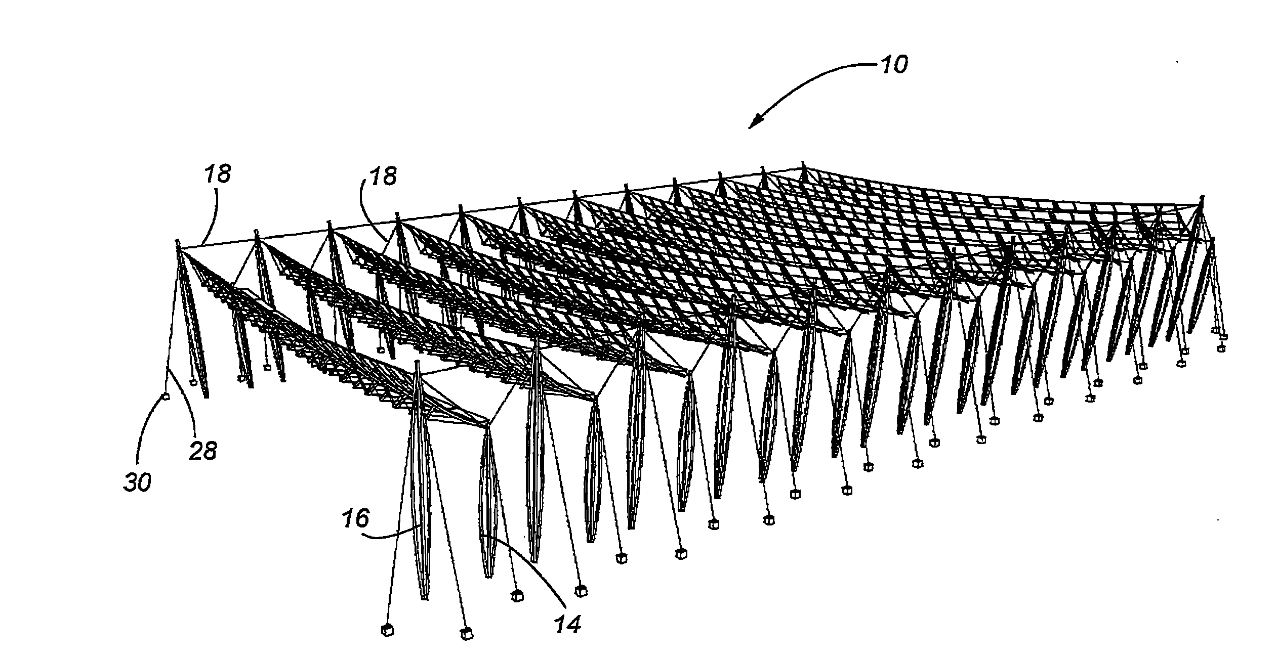
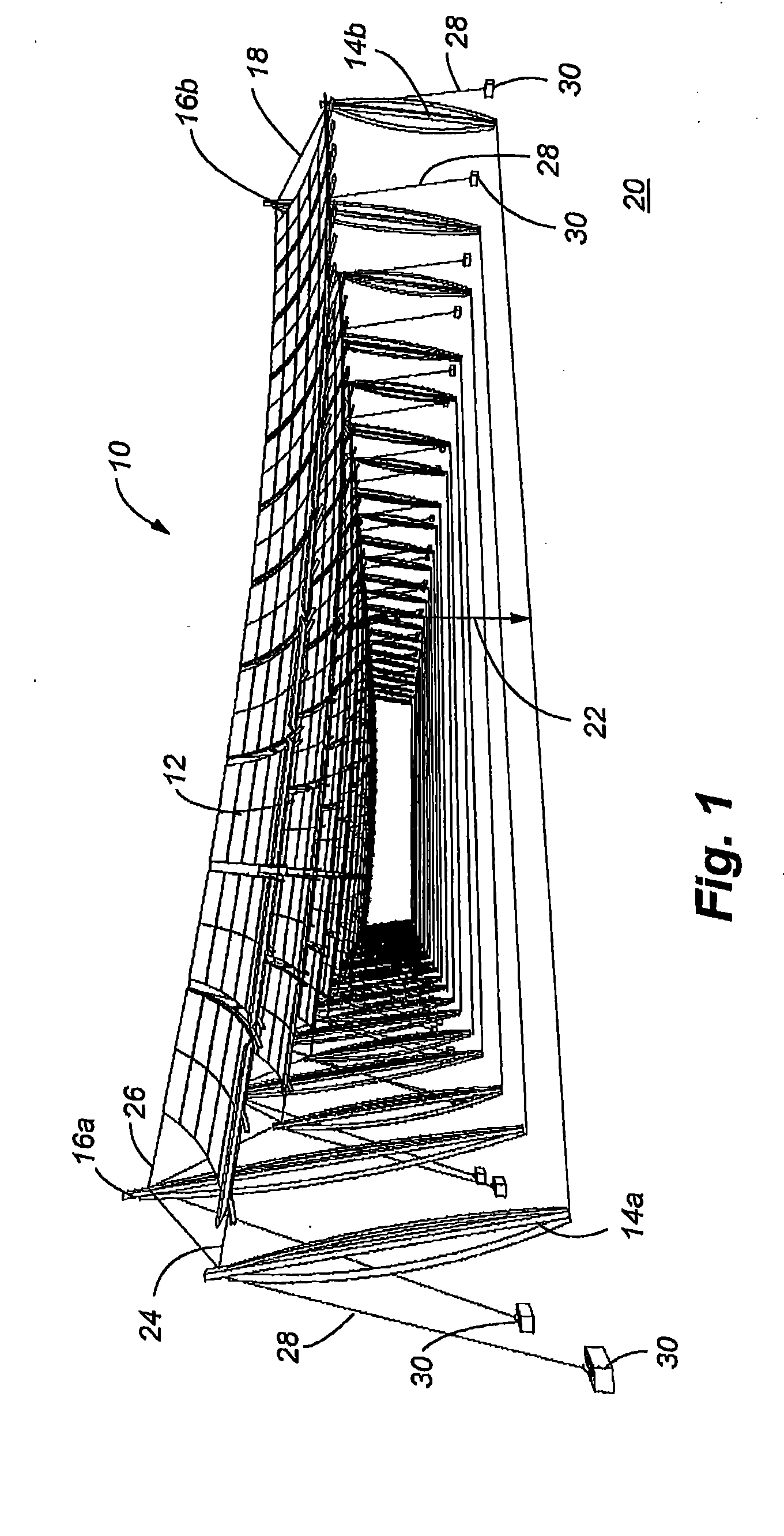
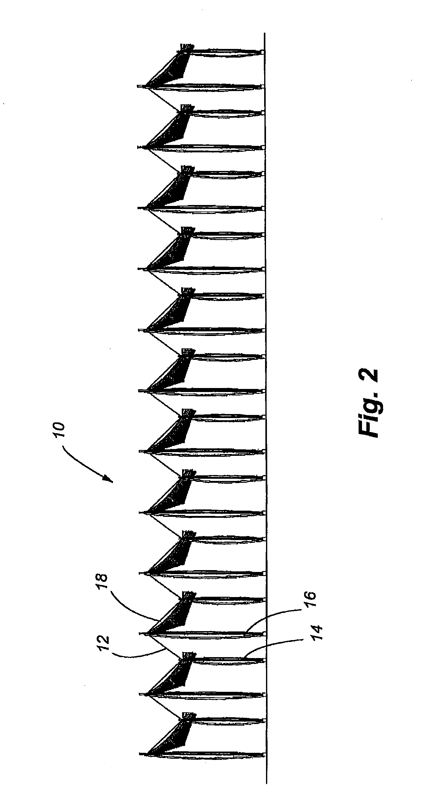
[0144]FIG. 1 is a perspective view of a solar panel array supported in accordance with an illustrative embodiment. A solar panel array 10 is illustrated as including a number of solar panel receivers or pods 12. Pairs of short columns 14a, 14b and tall columns 16a, 16b are aligned with one another. The pairs of columns 14a, 16a and 14b, 16b may also be connected by a stability cable 18 that runs along the edges of the array 10. The solar panel receivers 12 are held above a surface 20 at a height 22 defined by the columns 14a, 14b, 16a, 16b. A first main cable 24 is suspended between the short columns 14a, 14b, and a second main cable 26 is suspended between the tall columns 16a, 16b. The solar panel receivers 12 are designed to be supported by the cables 24, 2...


PUM


Abstract

Systems and methods for disposing and supporting a solar panel array are disclosed. The embodiments comprise various combinations of cables, support columns, and pod constructions in which to support solar panels. The solar panels can incorporate single or dual tracking capabilities to enhance sunlight capture. The embodiments encourage dual land use in which installation of the systems minimizes disruption of the underlying ground. Supplemental power may be provided by vertical axis windmills integrated with the columns. Special installations of the system can include systems mounted over structures such as parking lots, roads and aqueducts.

Description

CROSS REFERENCE TO RELATED APPLICATIONS[0001]This application is a continuation-in-part of U.S. application Ser. No. 12 / 255,178, filed on Oct. 21, 2008 entitled “Solar Array Support Methods and Systems, which is a continuation-in-part application of U.S. application Ser. No. 12 / 143,624, filed on Jun. 20, 2008 entitled, “Solar Array Support Methods and Systems”, which is a continuation-in-part application of U.S. application Ser. No. 12 / 122,228, filed on May 16, 2008, entitled “Solar Array Support Methods and Systems”, which is a continuation-in-part of U.S. application Ser. No. 11 / 856,521, filed on Sep. 17, 2007, entitled “Solar Array Support Methods and Systems”, which is a continuation application of U.S. application Ser. No. 10 / 606,204, filed Jun. 25, 2003, now the U.S. Pat. No. 7,285,719, entitled “Solar Array Support Methods and Systems”, which claims priority from Provisional Application Ser. No. 60 / 459,711, filed Apr. 2, 2003, entitled “Solar Sculpture Energy and Utility Arra...

Claims


Application Information

Patent Timeline
Patent Type & Authority Applications(United States)
IPC IPC(8): F24J2/00
CPCF24J2/5241H02S20/00Y02E10/50Y02E10/47F24S25/50H02S20/10H02S20/32
Inventor CONGER, STEVEN J.
Owner P4P HLDG
Why Eureka
Try Eureka