Method and apparatus for cleaning a jet engine

a jet engine and jet engine technology, applied in the direction of machines/engines, manufacturing tools, cleaning using liquids, etc., can solve the problems of increasing environmental pollution, reducing efficiency, and increasing fuel consumption

Active Publication Date: 2010-01-07
LUFTHANSA TECH AG
View PDF12 Cites 30 Cited by
  • Summary
  • Abstract
  • Description
  • Claims
  • Application Information

AI Technical Summary

Benefits of technology

[0013]Pellets can be produced from liquid CO2 in a pelletizer, as it is known, and are easily storable. There may be provision for the supply device to convey already prefabricated pellets to the nozzle device with the aid of a propellant gas. It is also possible, however, that the supply device has an apparatus for forming carbon dioxide pellets from liquid carbon dioxide and conveys these to the nozzle device by means of a propellant gas. In both instances, the solid carbon dioxide emerges from the nozzles of a nozzle device and passes into the engine to be cleaned.
[0037]Preferably, the set angle of the jet planes of the nozzles with the axis of rotation is adapted to the set angle of the compressor stage blades located at the front in the direction of flow of the engine. The cleaning action in the rear compressor stages or the combustion chamber and the turbine stages is thereby improved.

Problems solved by technology

A contamination of an aircraft jet engine may lead to a reduction in efficiency, thus resulting in an increased fuel consumption and consequently in increased environmental pollution.
Parts of the engine may be contaminated by combustion residues from the combustion chamber.
These impurities form a coating on those parts of an aircraft engine through which air flows, and are detrimental to the surface quality.
The thermodynamic efficiency of the engine is consequently impaired.
However, the surface of the engine parts is also attacked by the coal dust, and therefore a cleaning medium such as coal dust is not suitable for the regular cleaning of aircraft engines.
Moreover, in cleaning with coal dust, undesirable residues of the cleaning material remain behind in the engine.

Method used


Image

  • Method and apparatus for cleaning a jet engine
  • Method and apparatus for cleaning a jet engine
  • Method and apparatus for cleaning a jet engine

Examples


Embodiment Construction

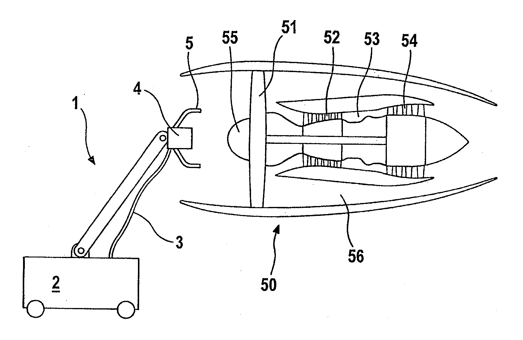
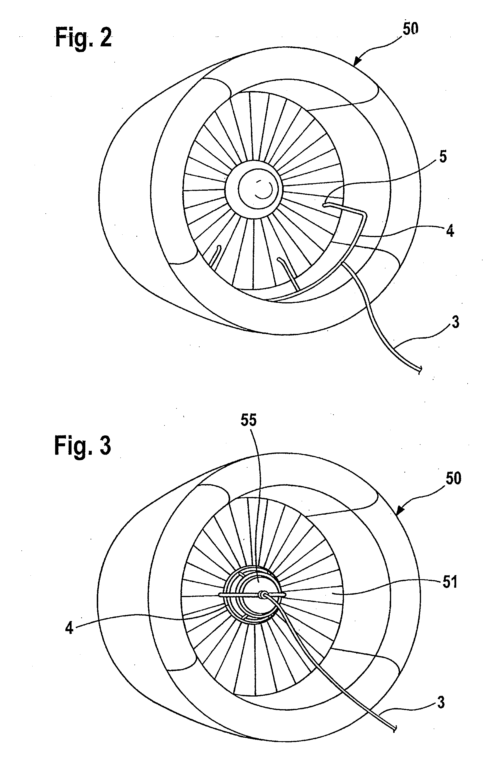
[0055]FIG. 1 illustrates a first apparatus 1 according to the invention for cleaning a jet engine 50.

[0056]The jet engine 50 is an engine with turbofan 51 and is illustrated as such diagrammatically. The engine 50 has, in addition to the turbofan 51, also a plurality of compressor stages 52, a combustion chamber 53 and turbine stages 54. Moreover, a shaft hub 55 is provided which is connected fixedly in terms of rotation to a turbofan. Part of the airstream, which passes through the turbofan 51 when the engine 50 is in operation, passes into the compressor stages 52 and subsequently into the combustion chamber 53 and the turbine stages 54; another part is conducted past these components in a secondary stream duct 56.

[0057]The apparatus 1 according to the invention consists of a supply device 2 comprising a tank for the cleaning medium which is suitable for storing liquid carbon dioxide, of a cooling device for cooling this tank and a pump. By means of the pump, the cleaning medium c...


PUM


Abstract

An apparatus for cleaning a jet engine includes a supply device configured to make cleaning medium available, a nozzle device configured to introduce the cleaning medium into the jet engine, and a line connection between the supply device and the nozzle device. The cleaning medium can be solid carbon dioxide. A system including a jet engine and the apparatus. A method for cleaning a jet engine using solid carbon dioxide.

Description

REFERENCE TO RELATED APPLICATIONS[0001]This application claims the priority of German Patent Application No. 10 2008 021 746.8, filed Apr. 30, 2008, the contents of which are incorporated herein by reference.FIELD OF THE INVENTION[0002]The invention relates to an apparatus, an arrangement and a method for cleaning an aircraft jet engine.BACKGROUND OF THE INVENTION[0003]Aircraft jet engines possess in a known way one or more compressor stages, a combustion chamber and also one or more turbine stages. In the turbine stages, the hot combustion gases coming from the combustion chamber discharge part of their thermal and mechanical energy which is utilized in order to drive the compressor stages. Jet engines of commercial aircraft nowadays have most predominantly what is known as a turbofan which is arranged upstream of the compressor stages and, as a rule, has a considerably larger diameter than the compressor stages. The turbofan is likewise driven by the turbine stages and allows a co...

Claims


Application Information

Patent Timeline
Patent Type & Authority Applications(United States)
IPC IPC(8): B08B7/00
CPCB08B3/02B08B9/00Y02T50/67B64F5/0018F01D25/002B24C1/003B64F5/30Y02T50/60
Inventor GILJOHANN, SEBASTIANPAUL, MANFRED
Owner LUFTHANSA TECH AG
Why Eureka
Try Eureka