
Girder block lifting method and jack-up stage used therefor

Inactive Publication Date: 2010-01-07
HITACHI LTD
View PDF5 Cites 31 Cited by
  • Summary
  • Abstract
  • Description
  • Claims
  • Application Information

AI Technical Summary

Benefits of technology

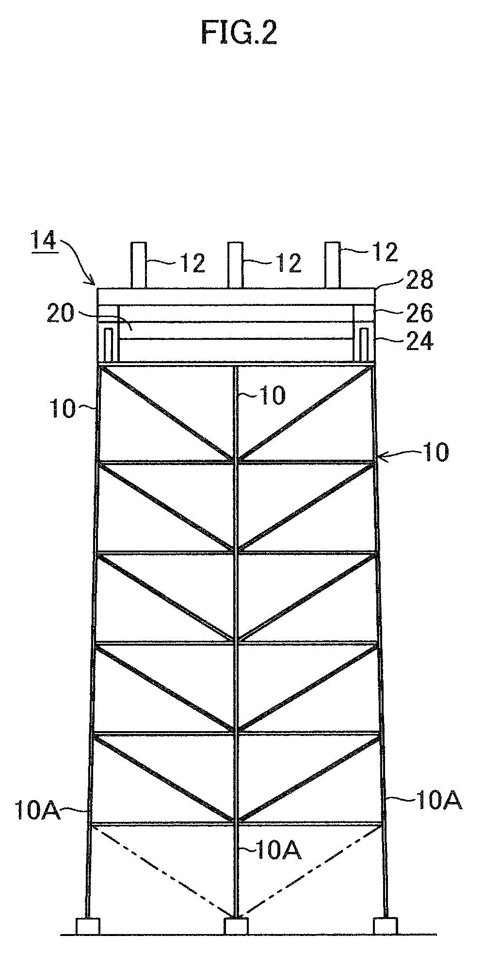
[0020]By the above-mentioned configuration, in the present invention, especially when constructing a thermal power plant, the jack-up stage constructs a rigid frame structure together with the steel beam and therefore even if the lifting weight is applied to the jack on the jack-up stage, only vertical load is applied and it becomes possible to prevent inward inclination or fall of the steel beams. Therefore, it becomes possible to lift up the girder block without constructing a large-scale truss frame for prevention of inclination or fall of the steel beam on the back surface side thereof.
[0021]Moreover, since the jack-up stage is configured to be temporarily connected to the top of the steel beam, it is not necessary to install the lifting jack or other related hydraulic machinery to the building structure including the steel beam. Therefore, it becomes possible to reuse the equipment including the lifting jack equipment in other construction sites.

Problems solved by technology

Therefore, there is a problem that the steel beams would incline or collapse inward due to lifting of heavy materials.
Therefore, in the conventional construction method, construction equipment becomes large due to the large frames 7 and 8 for supporting the steel beam and there occurs a problem that the construction cost becomes high.
Further, if the girder joint portion is shaped to have a special shape, there is a problem that the steel beam cannot be used for other construction methods using a girder which has a standard specification of other company.

Method used


Image

  • Girder block lifting method and jack-up stage used therefor
  • Girder block lifting method and jack-up stage used therefor
  • Girder block lifting method and jack-up stage used therefor

Examples


Embodiment Construction

[0031]Hereinafter, an embodiment of a girder block lifting method and a jack-up stage used therefor according to the present invention will be explained in detail based on an example where the present invention is applied to lifting of a boiler module of a thermal power plant with reference to the drawings. Here, the following embodiment is just an embodiment example and various modifications may be made without departing from the scope and spirit of the invention.

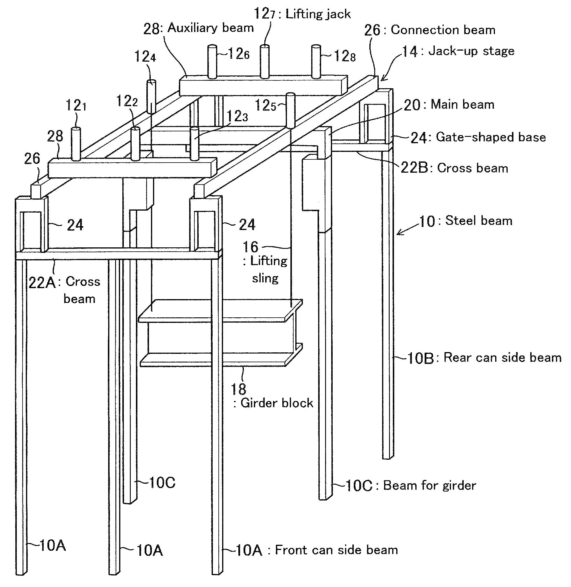
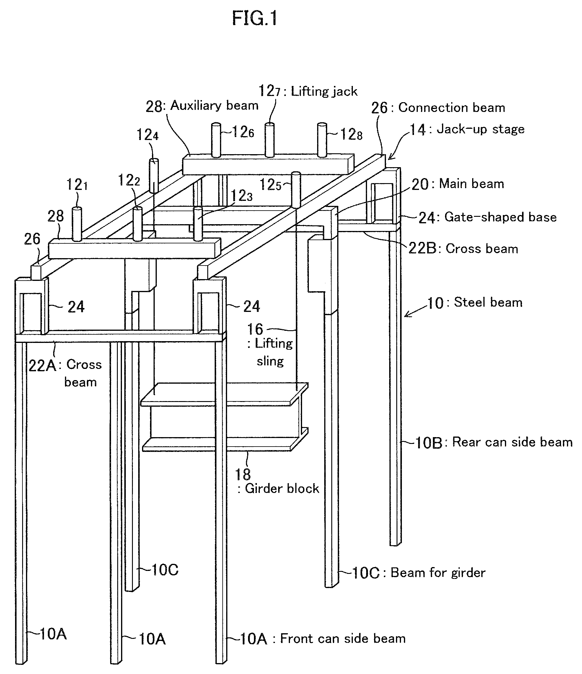
[0032]FIG. 1 is an explanatory view schematically showing a girder block lifting operation condition and is a perspective view showing a condition where a girder block which is to be lifted (a center sill block and a boiler module which is hung are omitted) is jacked up.

[0033]Six steel beams 10 of building frame part of a thermal power plant are set up in advance. The steel beams 10 include three beams 10A on a front can portion side, three beams 10B on a rear can portion side, and two later-described beams for a girder 10...


PUM


Abstract

A girder block lifting method, which can solve a problem that steel beams are inclined or fallen inward by lifting a heavy material, and a jack-up stage used therefor are provided. The method includes a main beam which can be provided between steel beams being targets of connection with the girder to construct a rigid frame structure, a height adjustment means (gate-shaped base) mounted on a cross beam member being parallel to the main beam and connecting other steel frames for adjusting height to the main beam, a connection beam for alternately connecting the main beam and the height adjustment means (gate-shaped base), and an auxiliary beam for connecting the connection beams. On a frame stage formed by connecting these beams, a plurality of lifting jacks are provided and a lifting sling is hung from upper part of the steel beam to enable jack-up of the girder block.

Description

BACKGROUND [0001](a) Field of the Invention[0002]The present invention relates to a girder block lifting method and a jack-up stage used therefor and especially relates to a girder block lifting method which is preferable when a boiler module for a thermal power plant is lifted by a girder of a steel frame for an installation work and a jack-up stage used therefor.[0003](b) Description of the Related Art[0004]In a thermal power plant having a large-scale pendant boiler, steel beams of a building are set and on top edge portions of the steel beam, a girder for supporting the boiler is provided to bridge the top edge portions and to support boiler component parts by hanging. For this configuration, a lifting construction method is generally used. In this method, modules of the boiler component parts carried in the steel frame are lifted up to the girder from the ground for several tens of meters by use of a plurality of lifting jacks provided on the girder and then the modules are hun...

Claims


Application Information

Patent Timeline
IPC IPC(8): B66C19/00B66F3/08B66F7/14
CPCB66C1/10F22B37/00B66C17/06B66C1/62
Inventor NAKAMITSU, KAZUHITOTAKESHITA, SHINICHIROKOJIMA, YOSHIMASAYANO, JIROYOKOI, YUJIKAWAGUCHI, SHIGEYOSHIHAMAKAWA, TETSUYATAZAWA, HIRONOBU
Owner HITACHI LTD
Learn More