Method of manufacturing magnetic recording medium

a manufacturing method and magnetic recording technology, applied in the direction of magnetic bodies, coating parts of support with magnetic layers, coating carrier supports, etc., can solve the problems of increasing the disturbance of enhancement of track density, affecting and reducing write blurring, so as to improve the magnetic characteristics of the irradiated portions and improve the accuracy of head positioning

Inactive Publication Date: 2010-01-07
KK TOSHIBA
View PDF15 Cites 110 Cited by
  • Summary
  • Abstract
  • Description
  • Claims
  • Application Information

AI Technical Summary

Benefits of technology

[0012]Jpn. Pat. Appln. KOKAI Publication No. 2005-223177 is to improve the magnetic characteristics of the irradiated portions by implanting heavy atoms into the magnetic recording layer. The medium has poor head positioning accuracy of about 20 nm, however, which does not satisfy a specified value of 10 nm or less. When the medium surface was observed with a magnetic force microscope (MFM), it was found that a magnetic shape of servo patterns was not favorable. This may be because heavy atom ions with high-energy are diffused to damage the magnetic recording layer.

Problems solved by technology

Recently, in the magnetic recording medium incorporated into hard disk drives (HDDs), there is an increasing problem of disturbance of enhancement of track density due to interference between adjacent tracks.
In particular, a serious technical subject is reduction of write blurring due to fringe effect of a magnetic field from a write head.
When a medium having an irregular surface formed thereon the DTR medium is read and write with a flying head, flying properties of the head are posed as a problem.
However, it is difficult to perform the flattening step.
PCT National Publication No. 2002-501300 using modification of the magnetic layer by nitrogen ions and He ions, cannot achieve enough separation between recording tracks.
The medium has poor head positioning accuracy of about 20 nm, however, which does not satisfy a specified value of 10 nm or less.
When the medium surface was observed with a magnetic force microscope (MFM), it was found that a magnetic shape of servo patterns was not favorable.
This may be because heavy atom ions with high-energy are diffused to damage the magnetic recording layer.

Method used


Image

  • Method of manufacturing magnetic recording medium
  • Method of manufacturing magnetic recording medium
  • Method of manufacturing magnetic recording medium

Examples


example 2

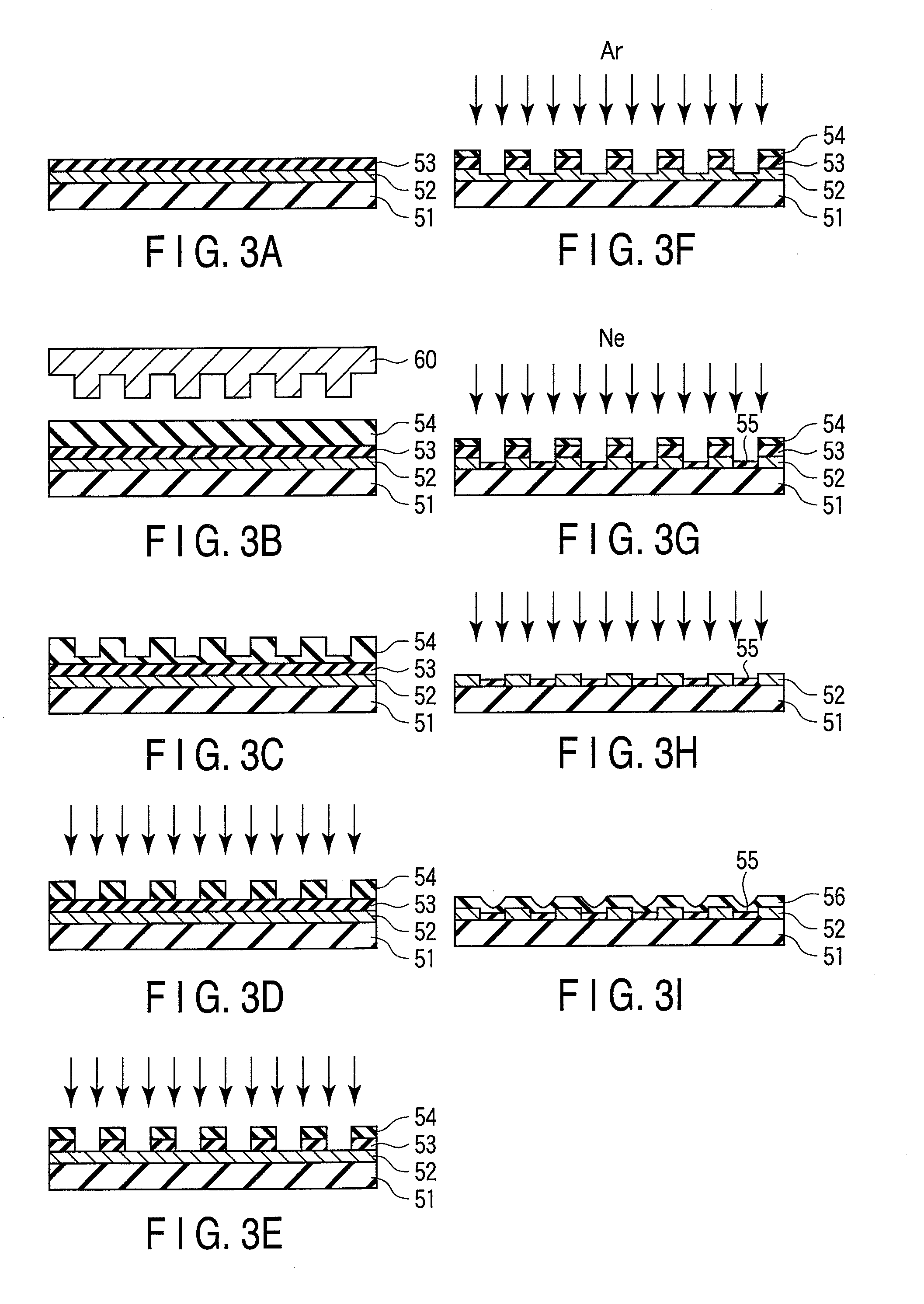
[0080]A DTR medium was manufactured by the method shown in FIGS. 4A to 4H. More specifically, in the step of FIG. 4F, etching and modification of the magnetic recording layer were simultaneously performed by using a mixture gas of Ar and Ne. The mixing ratio of the Ar gas to the Ne gas was set to 80% to 20% (flow rates of Ar and Ne were 20 sccm and 5 sccm), processing was performed with an ECR ion gun at an acceleration voltage of 1000V and adjusted such that the depth of the recesses was 10 nm.

[0081]When the resultant DTR medium was evaluated for a glide test, the medium passed the glide test using a 8-nm flying head. When the resultant DTR medium was mounted on a drive and measured for on-track BER, the power of −4.5 was obtained. The positioning accuracy of the read / write head was 6 nm. When the medium was evaluated for a fringe test, the medium exhibited preferable fringe resistance. When the medium was evaluated for reliability test at a temperature of 65° C. and a humidity of ...


PUM


Abstract

According to one embodiment, a method of manufacturing a magnetic recording medium includes depositing a magnetic recording layer on a substrate, forming masks on areas corresponding to recording regions of the magnetic recording layer, partially etching the magnetic recording layer in areas not covered with the masks with an etching gas to form protrusions and recesses on the magnetic recording layer, modifying the magnetic recording layer remaining in the recesses with Ne gas to form non-recording regions, and forming a protecting film on an entire surface.

Description

CROSS-REFERENCE TO RELATED APPLICATIONS[0001]This is a Continuation Application of PCT Application No. PCT / JP2008 / 071915, filed Nov. 26, 2008, which was published under PCT Article 21(2) in English.[0002]This application is based upon and claims the benefit of priority from Japanese Patent Application No. 2008-021904, filed Jan. 31, 2008, the entire contents of which are incorporated herein by reference.BACKGROUND[0003]1. Field[0004]The present invention relates to a method of manufacturing a magnetic recording medium.[0005]2. Description of the Related Art[0006]Recently, in the magnetic recording medium incorporated into hard disk drives (HDDs), there is an increasing problem of disturbance of enhancement of track density due to interference between adjacent tracks. In particular, a serious technical subject is reduction of write blurring due to fringe effect of a magnetic field from a write head.[0007]To solve such a problem, for example, a discrete track recording-type patterned ...

Claims


Application Information

Patent Timeline
Patent Type & Authority Applications(United States)
IPC IPC(8): B44C1/22
CPCG11B5/855H01F10/265H01F41/34H01F10/12
Inventor KAMATA, YOSHIYUKIISOWAKI, YOSUKEKIMURA, KAORISHIROTORI, SATOSHISAKURAI, MASATOSHI
Owner KK TOSHIBA
Why Eureka
Try Eureka