Wave soldering tank

Active Publication Date: 2010-01-07
SENJU METAL IND CO LTD
View PDF3 Cites 5 Cited by
  • Summary
  • Abstract
  • Description
  • Claims
  • Application Information

AI Technical Summary

Benefits of technology

[0024]A wave soldering tank according to the present invention does not require precise finishing of the gap between the screw pump and a casing, and it can be inexpensively manufactured. According to the present invention, even if the screw pump or the casing deforms to a certain extent due to thermal expansion and contraction of solder, the screw pump does not rub against and is not pressed against the casing, and the screw pump can stably rotate. In a wave soldering tank according to the present invention, as the diameter of the inlet formed in the bottom of the casing is smaller than the diameter of the screw pump, when molten solder which is sucked in by the screw pump flows backwards between the screw pump and the casing, it is obstructed by the inner flange of the inlet and does not flow out from the inlet. Namely, in a wave soldering tank according to the present invention, molten solder which is sucked in by the screw pump does not become turbulent. Therefore, it does not become turbulent when it leaves the screw pump and flows through the duct, and it does not undergo pulsation when it spouts from the discharge nozzle. As a result, a wave soldering tank according to the present invention can always stably contact molten solder with the surface to be soldered of a printed circuit board, and reliable soldered portions are obtained.BRIEF EXPLANATION OF THE DRAWINGS
[0025]FIG. 1—This is a front cross-sectional view of a wave soldering tank according to the present invention.
[0026]FIG. 2—This is an enlarged partially cross-sectional perspective view of important parts.
[0027]FIG. 3—This is a cross-sectional view along line X-X of FIG. 1.
[0028]FIG. 4—This is a view explaining the flow of molten solder in a screw pump of a wave soldering tank according to the present invention.
[0029]FIG. 5—This is a view explaining the flow of molten solder in a screw pump of a conventional wave soldering tank.EXPLANATION OF SYMBOLS

Problems solved by technology

However, with an impeller pump, pulsation of the solder spouted from the discharge nozzle is sometimes experienced.

Method used


Image

  • Wave soldering tank
  • Wave soldering tank
  • Wave soldering tank

Examples


Embodiment Construction

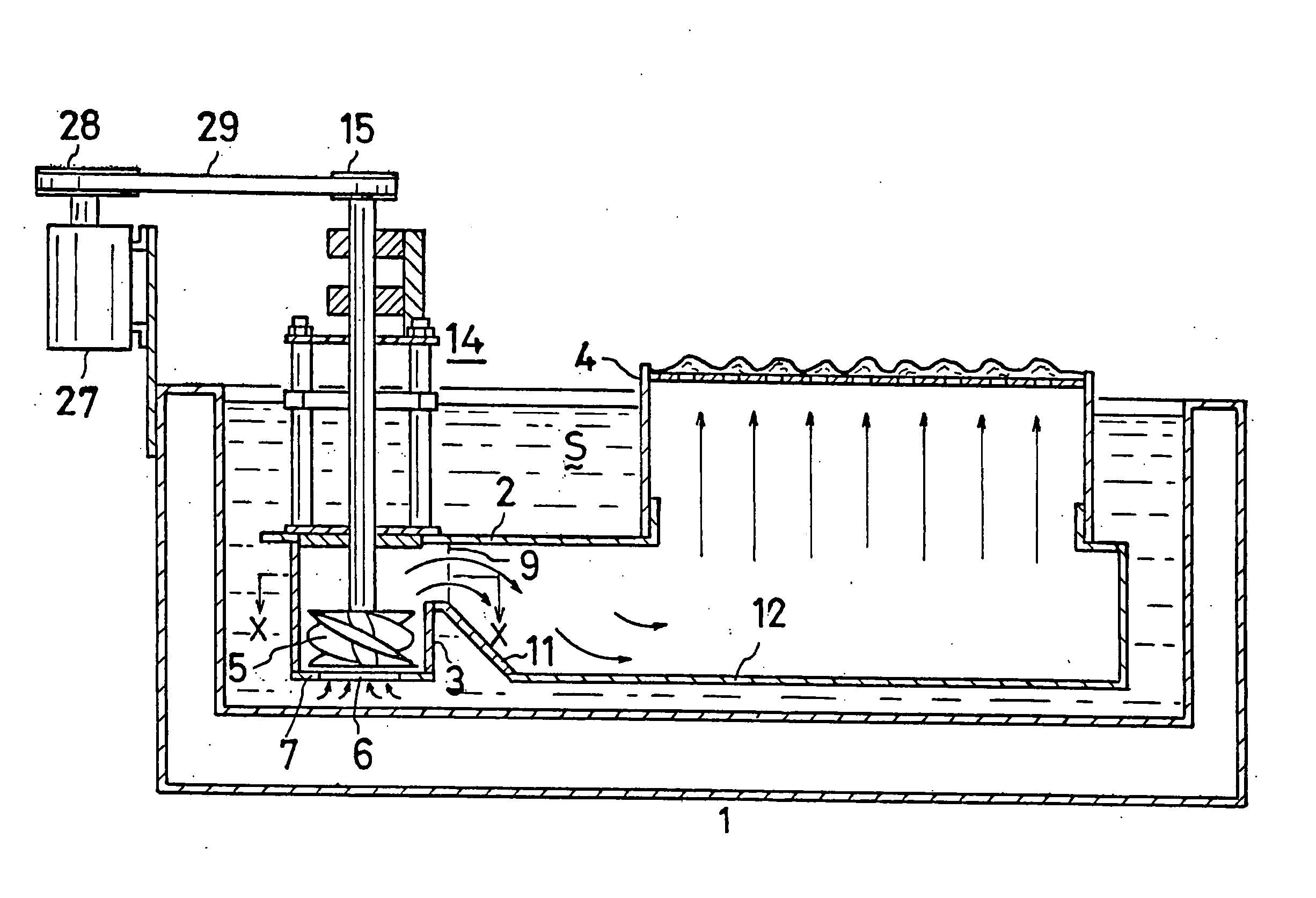
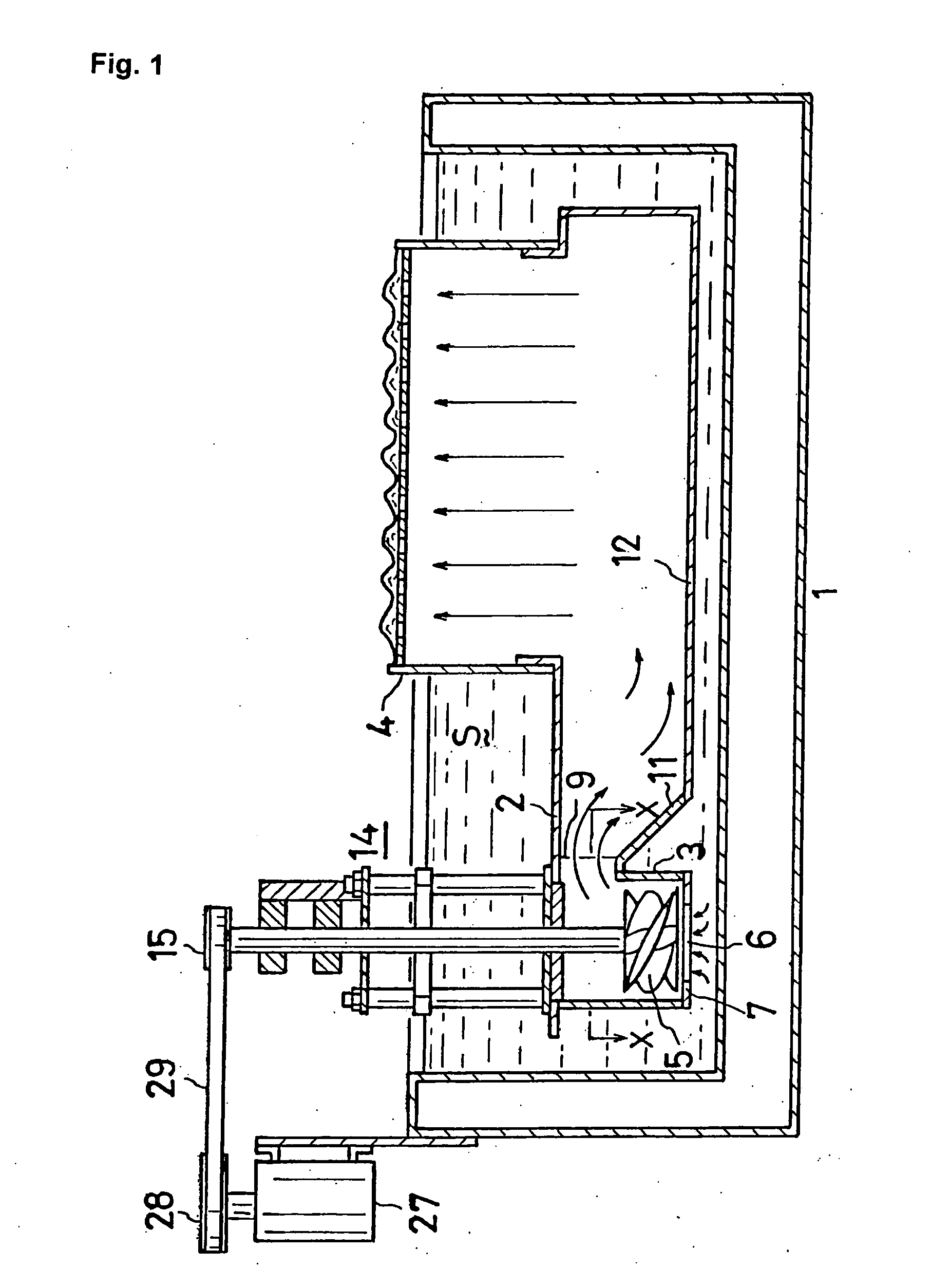
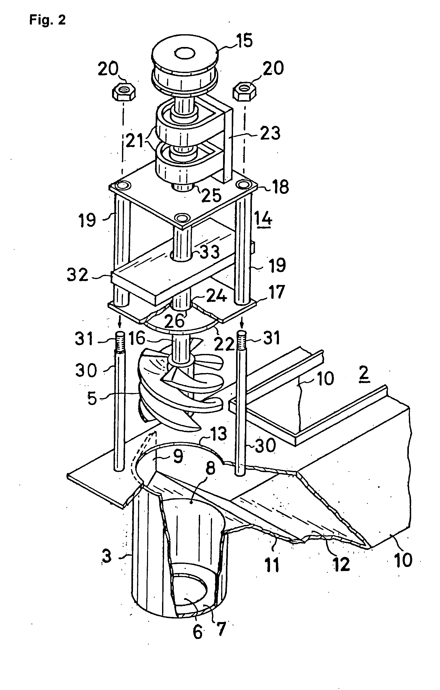
[0040]Below, a wave soldering tank according to the present invention will be explained based on the drawings. FIG. 1 is a front cross-sectional view of a wave soldering tank according to the present invention, FIG. 2 is an enlarged partially cross-sectional perspective view of important portions, FIG. 3 is a cross-sectional view taken along line X-X of FIG. 1, and FIG. 4 is a view for explaining the flow of molten solder in a screw pump of a wave soldering tank according to the present invention.

[0041]A wave soldering tank according to the present invention has a lidless box-shaped body 1. A duct 2 is installed inside the body. A casing 3 is installed at one end of the duct 2, and a discharge nozzle 4 is installed at the upper portion of the other end. A screw pump 5 is installed inside the casing 3 with a suitable gap G, such as a gap of a size such that the screw pump will not contact the casing even if the screw pump develops a certain amount of eccentricity due to thermal expan...


PUM

PropertyMeasurementUnit
Flow rateaaaaaaaaaa
Diameteraaaaaaaaaa

Abstract

In a wave soldering tank using a conventional screw pump, pulsation sometimes occurred in which molten solder spouting from the discharge nozzle moved up and down. The cause of the occurrence of the pulsation in a screw pump was that the gap between the screw pump and the casing was wide, so there was reverse flow through the gap. It is conceivable to narrow the gap, but if the gap is made narrow, the screw pump ends up contacting the casing if the screw pump becomes eccentric.A wave soldering tank according to the present invention makes the diameter of the inlet in the bottom of the casing smaller than the diameter of the screw pump so that reverse flow does not take place even if the gap between the screw pump and the casing is wide. Flow is made more stable by providing outwardly flaring guide walls on the outlet of the casing.

Description

TECHNICAL FIELD [0001]This invention relates to a wave soldering tank which is installed in an automatic soldering apparatus and which carries out soldering of printed circuit boards.BACKGROUND ART [0002]In an automatic soldering apparatus, processing equipment such as a fluxer, a preheater, a wave soldering tank, and a cooler are arranged in series, and a conveyor runs above the processing equipment. While being transported by the conveyor, a printed circuit board undergoes flux application in the fluxer, preheating in the preheater, adhesion of solder in the wave soldering tank, and cooling in the cooler to carry out soldering.[0003]All of the processing equipment in an automatic soldering apparatus affects the quality of soldering, but the wave soldering tank has a particularly great effect. For example, the wave soldering tank must not have pulsing in which the height of spouted solder moves up and down, and oxides which are floating in molten solder must not be enveloped therei...

Claims


Application Information

Patent Timeline
IPC IPC(8): B23K31/02
CPCB23K1/0016B23K1/085H05K3/3468B23K2201/42B23K3/0653B23K2101/42
Inventor ZEN, MITSUOICHIKAWA, HIROKAZUOZAWA, SATOSHI
Owner SENJU METAL IND CO LTD
Why Eureka
Try Eureka