Piston cooling jet with tracking ball orifice

a technology of cooling jet and tracking ball, which is applied in the direction of functional valve types, machines/engines, other domestic objects, etc., can solve the problems of reducing the cooling and lubricating effect of oil, affecting the cooling effect of oil, so as to reduce agitation and aeration, reduce the cost of production, and increase the cost of manufacture

a technology of cooling jet and tracking ball, which is applied in the direction of functional valve types, machines/engines, other domestic objects, etc., can solve the problems of reducing the cooling and lubricating effect of oil, affecting the cooling effect of oil, so as to reduce agitation and aeration, reduce the cost of production, and increase the cost of manufacture

US20100001103A1Inactive Publication Date: 2010-01-07METALDYNE LLC

Image

  • Piston cooling jet with tracking ball orifice
  • Piston cooling jet with tracking ball orifice
  • Piston cooling jet with tracking ball orifice

Examples


Embodiment Construction

[0033]While the present oil jet is described with reference to an exemplary embodiment described herein, it should be clear that the present oil jet should not be limited to such an embodiment. Therefore, the description of the embodiment provided herein is illustrative of the present invention and should not limit the scope of the invention as claimed.

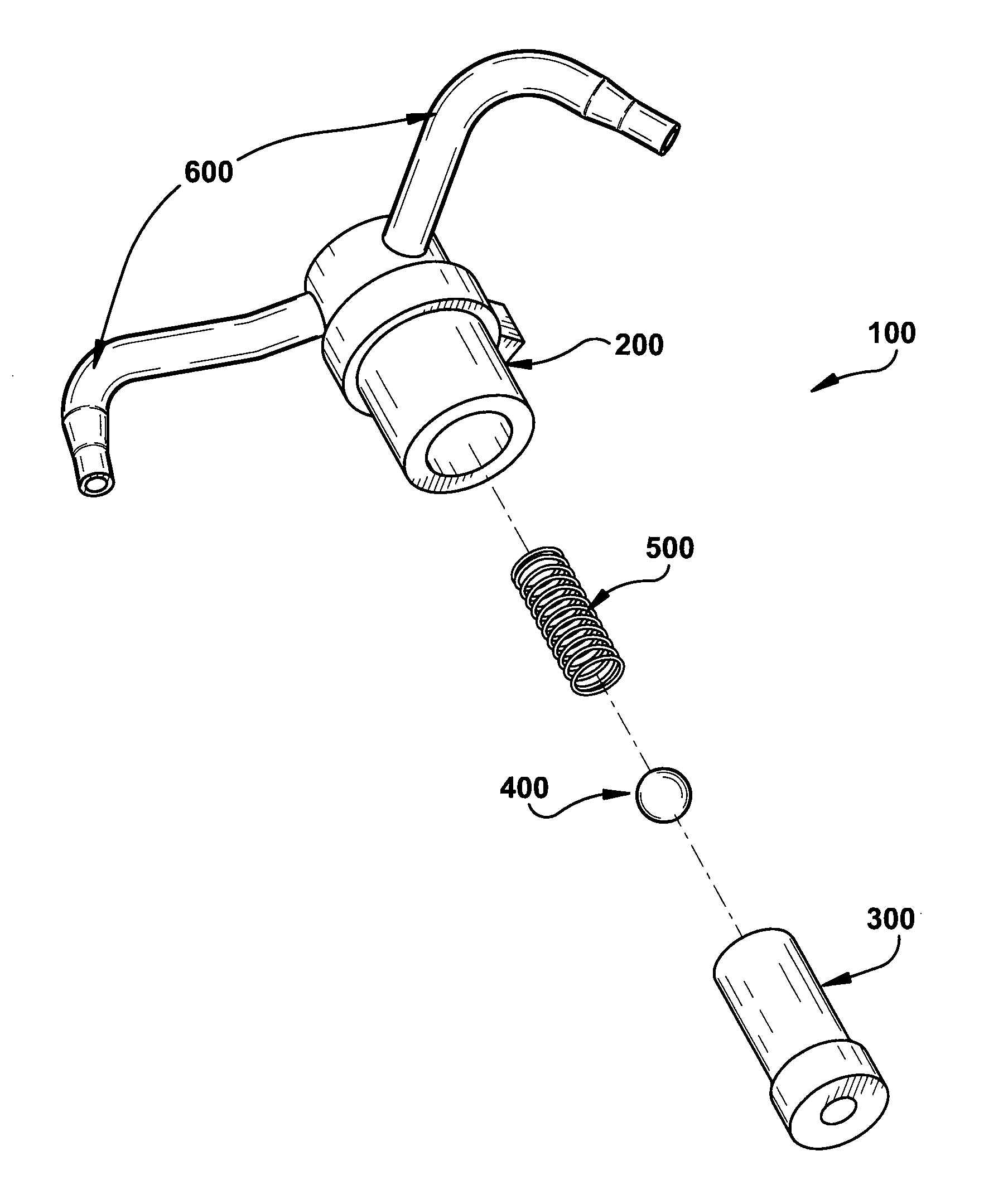
[0034]An exemplary embodiment of an oil jet 100 is illustrated in FIGS. 4-6. The oil jet 100 may be arranged to provide oil to the underside of one or more reciprocating pistons in an engine. The oil may be delivered to the pistons when the oil pressure of the engine exceeds a predetermined threshold. The oil may cease to be delivered to the pistons when the oil pressure of the engine falls below the predetermined threshold. The oil jet 100 may include a main body 200, an insert cap 300, a ball 400, a compression spring 500, and one or more tubes 600.

[0035]The main body 200 may be a one-piece component constructed from a powdered meta...


PUM

PropertyMeasurementUnit
areaaaaaaaaaaa
pressureaaaaaaaaaa
temperaturesaaaaaaaaaa

Abstract

An oil jet assembly includes a body, a tube, a cap insert, a ball, and a spring. The body includes a bore passing longitudinally through the body; a tube aperture passing through the body near a first end of the body; and an opening at a second and opposite end of the body. The tube is attached to the body and in fluid communication with the tube aperture. The cap insert is positioned within the bore of the body. The cap insert includes a bore that passes longitudinally through the cap insert to form a wall. The cap insert also includes an oil exit aperture passing though the wall and is in fluid communication with the bore of the body. The ball and spring are positioned within the bore of the insert cap. The spring is positioned between the ball and the first end of the body.

Description

CROSS-REFERENCE TO RELATED APPLICATIONS[0001]This application claims priority from U.S. Provisional Patent Application No. 60 / 967,885 entitled “PISTON COOLING JET WITH TRACKING BALL ORIFICE” filed on Sep. 7, 2007, which is hereby incorporated by reference in its entirety.FIELD OF THE INVENTION[0002]The present invention relates generally to fluid jets for providing fluid under pressure to a desired location, and more particularly, to a fluid jet having a stable ball valve assembly.BACKGROUND OF THE INVENTION[0003]Pistons used in gasoline engines, diesel engines, and high performance engines become easily overheated during operation. Pressure actuated oil jets have been used to cool the under side of pistons in such reciprocating engines. Oil jets are often mounted in a bore on the underside of the engine block and receive oil under pressure from an oil gallery. These oil jets also incorporate a check valve to supply oil to the oil jet when a predetermined oil pressure is achieved. O...

Claims


Application Information

Patent Timeline
07 Jan 2010
Publication
US20100001103A1
IPC
B05B1/30; B23P17/00; F01P3/08
CPC
F01M1/08; Y10T29/49417; F01P3/08; Y10T137/7927
Inventors
NETO, JOSE CORREA; POTTER, JR., TRUMAN ALLEN