Deterioration determination circuit, power supply apparatus, and deterioration determination method of secondary battery

a secondary battery and deterioration determination technology, applied in secondary cell servicing/maintenance, instruments, electrochemical generators, etc., can solve the problems of internal resistance increase, loss, safety degradation, etc., and achieve the effect of improving the accuracy of deterioration determination of secondary batteries

Active Publication Date: 2010-01-07
PANASONIC CORP
View PDF5 Cites 68 Cited by
  • Summary
  • Abstract
  • Description
  • Claims
  • Application Information

AI Technical Summary

Benefits of technology

[0021]According to the foregoing deterioration determination circuit, the power supply apparatus, and the deterioration determination method of a secondary battery, since with regard to the SOC of the secondary battery the secondary battery is ultimately determined to be deteriorated when the obtained internal resistance values both show the deterioration of the secondary battery respectively in a first range and a second range in which the

Problems solved by technology

With this kind of photo voltaic system, when the secondary battery is fully charged, loss will arise since the surplus power can no longer be charged.
Meanwhile, if deterioration advances in this kind of secondary battery, the internal resistance will increase.
Consequently, even if the secondary battery is used in the same manner as its initial state without any deterioration, if the deterioration advances, the temperature will rise pursuant to the heat generation of the secondary battery, and the safety will deteriorate.
Thus, if the deterioration of the secondary battery is determined based on the internal re

Method used


Image

  • Deterioration determination circuit, power supply apparatus, and deterioration determination method of secondary battery
  • Deterioration determination circuit, power supply apparatus, and deterioration determination method of secondary battery
  • Deterioration determination circuit, power supply apparatus, and deterioration determination method of secondary battery

Examples


Embodiment Construction

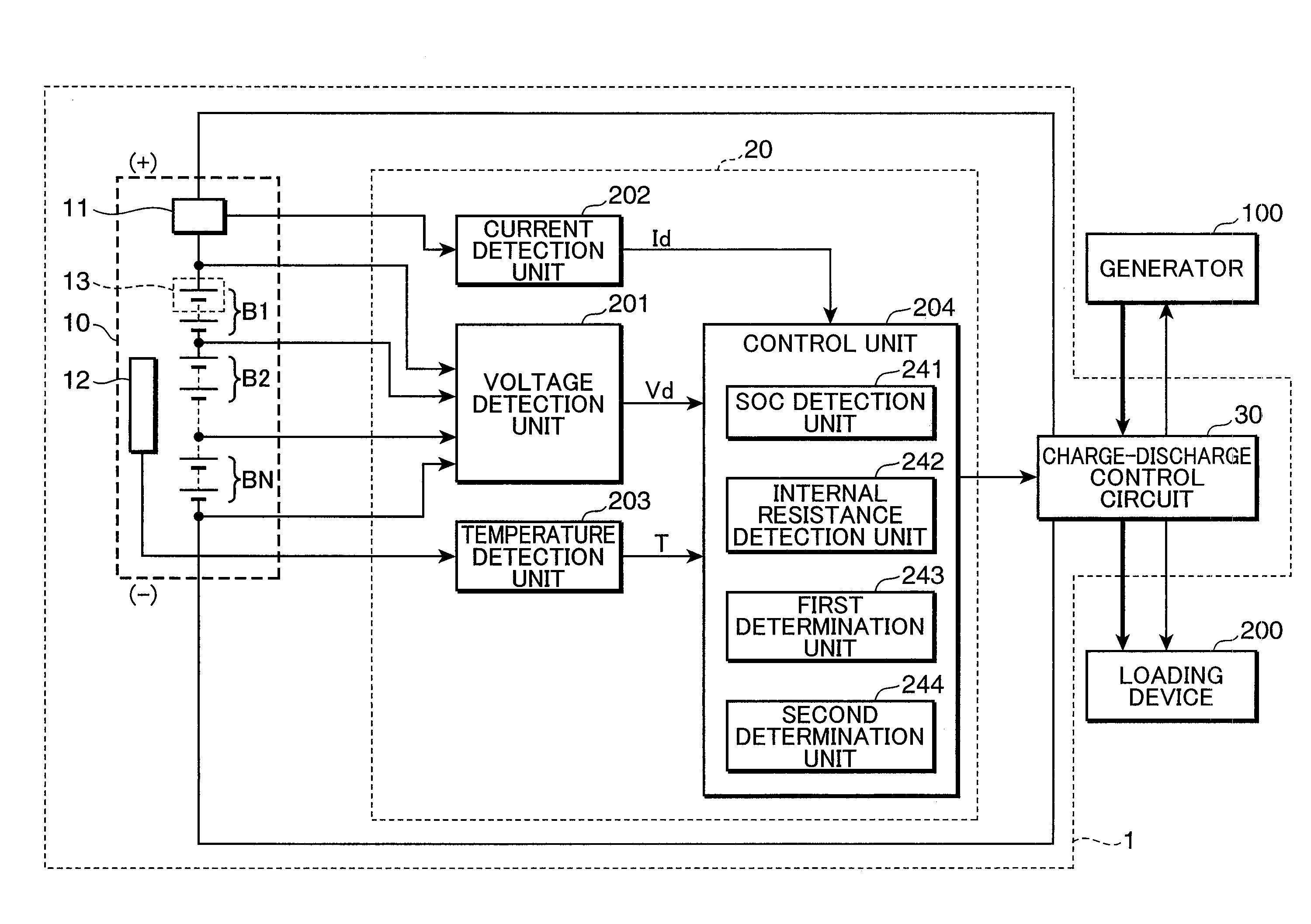
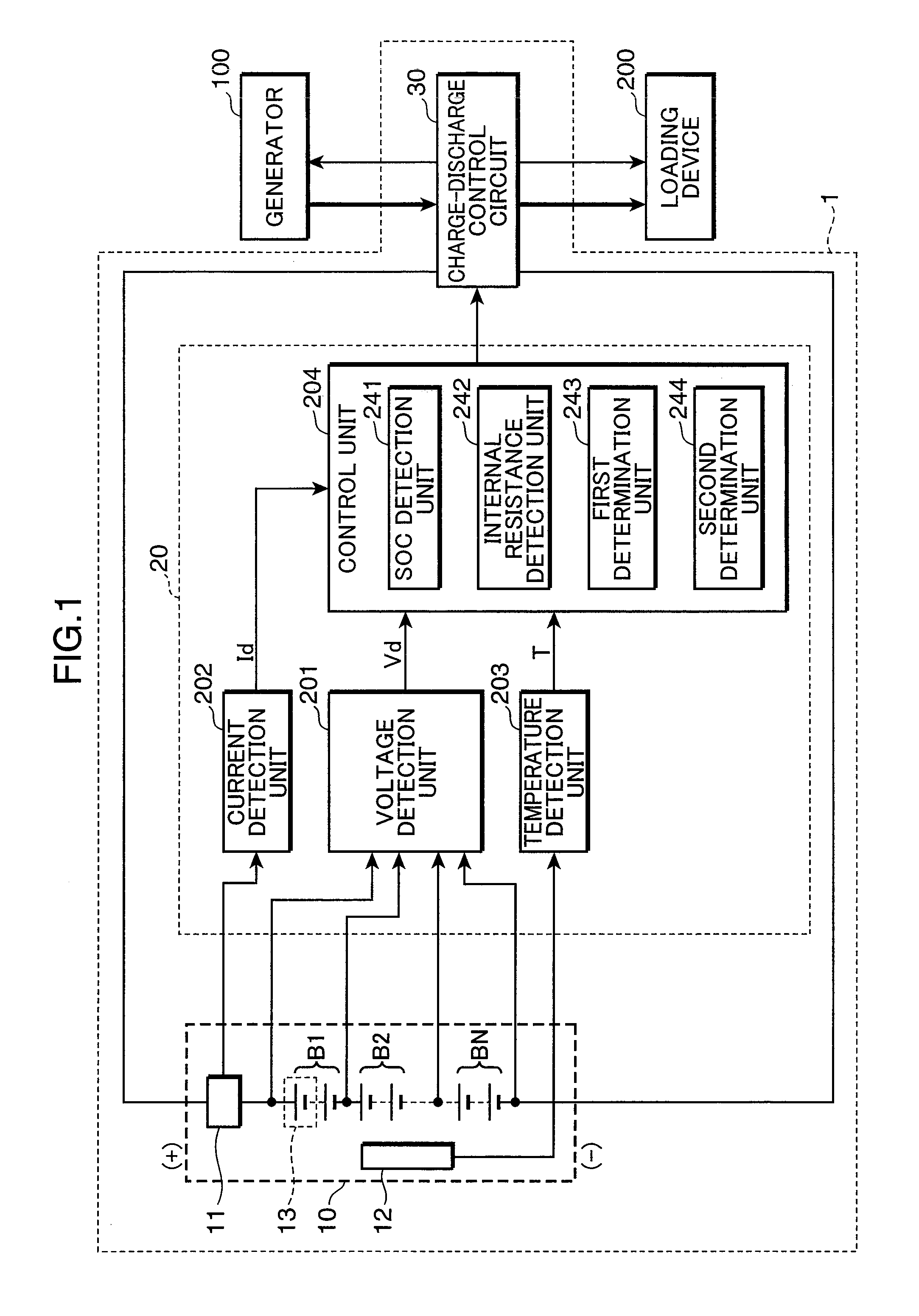
[0027]Embodiments of the present invention are now explained with reference to the attached drawings. Incidentally, the following embodiments are merely embodied examples of the present invention, and are not intended to limit the technical range of this invention in any way. In addition, configurations that are given the same reference numeral in the respective drawings show that they are the same configuration, and the explanation thereof is omitted. FIG. 1 is a block diagram showing an example of the configuration of a deterioration determination circuit applying the deterioration determination method of a secondary battery and a power supply apparatus employing such deterioration determination circuit according to an embodiment of the present invention.

[0028]The power supply apparatus 1 shown in FIG. 1 comprises a secondary battery 10, a deterioration determination circuit 20, and a charge-discharge control circuit 30 (charge-discharge control unit). The power supply apparatus 1...


PUM


Abstract

Provided is a deterioration determination circuit configuring by including: an SOC detection unit for detecting an SOC of a secondary battery; an internal resistance detection unit for detecting an internal resistance value of the secondary battery; a first determination unit for determining the status of deterioration of the secondary battery based on the internal resistance value detected by the internal resistance detection unit when the SOC detected by the SOC detection unit is within a range of a pre-set first range; a second determination unit for determining the status of deterioration of the secondary battery based on the internal resistance value detected by the internal resistance detection unit when the SOC detected by the SOC detection unit is within a range of a pre-set second range as a range of an SOC, in which a variation of the internal resistance of the second battery in relation to a variation of the SOC of the secondary battery is different from the first range; and a final determination unit for ultimately determining that the secondary battery is deteriorated when the first determination unit determines that the secondary battery is of the deteriorated status and the second determination unit additionally determines that the secondary battery is of the deteriorated status.

Description

BACKGROUND OF THE INVENTION[0001]1. Field of the Invention[0002]The present invention relates to a deterioration determination circuit for determining the status of determination of a secondary battery, a power supply apparatus comprising such a deterioration determination circuit, and a deterioration determination method for a secondary battery.[0003]2. Description of the Background Art[0004]In recent years, a secondary battery is being combined with a solar battery or a generator and broadly used as a power system. A generator is driven with natural energy such as wind power or water power, or artificial power such as an internal combustion engine. This kind of power system including a secondary battery accumulates surplus electric power in the secondary battery, and a loading device supplies electric power from the secondary battery as needed so as to improve the energy efficiency.[0005]As an example of this kind of system, there is a photo voltaic system. With this photo voltaic...

Claims


Application Information

Patent Timeline
IPC IPC(8): H02J7/00G01N27/416
CPCG01R31/3679H01M10/345H01M10/48H01M10/4285H01M10/425G01R31/392Y02E60/10
Inventor IIDA, TAKUMATANIGUCHI, AKIHIRONAKASHIMA, TAKUYA
Owner PANASONIC CORP
Why Eureka
Try Eureka