Domain crossing circuit and method

Inactive Publication Date: 2010-01-07
SK HYNIX INC
View PDF6 Cites 44 Cited by
  • Summary
  • Abstract
  • Description
  • Claims
  • Application Information

AI Technical Summary

Benefits of technology

[0035]Embodiments of the present invention are directed to a domain

Problems solved by technology

Whenever the internal clock is toggled, the replica delay unit consumes lots of current, which substantially i

Method used


Image

  • Domain crossing circuit and method
  • Domain crossing circuit and method
  • Domain crossing circuit and method

Examples


Embodiment Construction

[0048]Other objects and advantages of the present invention can be understood by the following description, and become apparent with reference to the embodiments of the present invention.

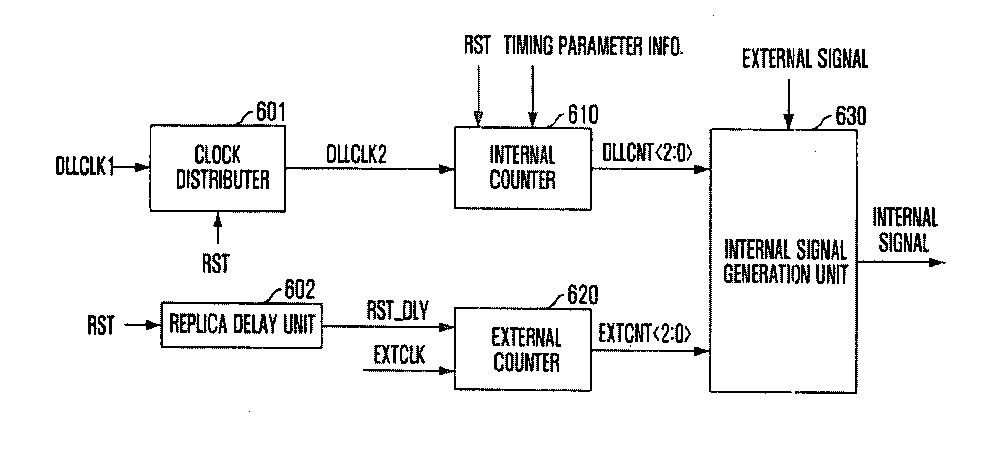
[0049]FIG. 6 illustrates a block diagram of a domain crossing circuit in accordance with an embodiment of the present invention.

[0050]Referring to FIG. 6, the domain crossing circuit includes a clock distributer 601, a replica delay unit 602, an internal counter 610, an external counter 620 and an internal signal generation unit 630.

[0051]The clock distributer 601 generates a clock DLLCLK2 in response to an internal clock DLLCLK1. The clock distributer 601 prevents toggling of the clock DLLCLK2 until a rest signal RST is released, and then, outputs the clock DLLCLK2 that is toggled if the reset signal RST is released. That is, the clocks DLLCLK1 and DLLCLK2 are the same internal clock. However, unlike the internal clock DLLCLK1, the internal clock DLLCLK2 maintains a constant level without being tog...


PUM


Abstract

A domain crossing circuit for reducing current consumption includes an internal counter to count an internal clock in response to the release of a reset signal, outputting an internal code, a replica delay unit to delay the reset signal as much as a timing difference between the internal clock and an external clock, outputting a delayed reset signal, an external counter to count the external clock in response to the release of the delayed reset signal outputted from the replica delay unit, outputting an external code, and an internal signal generation unit to convert an external signal to an internal signal using the internal code and the external code.

Description

CROSS-REFERENCE TO RELATED APPLICATION[0001]The present invention claims priority of Korean patent application number 10-2008-0064397, filed on Jul. 3, 2008, which is incorporated by reference in its entirety.BACKGROUND OF THE INVENTION[0002]The present invention relates to a domain crossing circuit, and more particularly, to a technology for reducing the current consumption of a domain crossing circuit.[0003]In general, a semiconductor memory device such as a double data rate synchronous DRAM (DDR SRAM) receives various commands synchronized with an external clock, operates in synchronization with an internal clock, and thus outputs data.[0004]That is, although the commands are inputted to the semiconductor memory device from the external in a state of being synchronized with the external clock, the semiconductor memory device performs internal operations in a state of being synchronized with the internal clock and outputs the data corresponding to the commands in synchronization w...

Claims


Application Information

Patent Timeline
IPC IPC(8): H03K19/00G11C11/407G11C11/4076H03K5/00H03K5/13
CPCG11C7/22G11C11/4076G11C7/222G11C7/20G11C11/4072G11C2207/2227
Inventor KIM, KYUNG-WHAN
Owner SK HYNIX INC
Why Eureka
Try Eureka