Passive repeater antenna

a repeater antenna and repeater technology, applied in the field of passive repeater antennas, can solve the problems of limiting the usefulness of the reflector, difficult to find a suitable installation site, etc., and achieve the effects of low loss, low cost of production, and high directivity

Inactive Publication Date: 2010-01-07
TELEFON AB LM ERICSSON (PUBL)
View PDF11 Cites 11 Cited by
  • Summary
  • Abstract
  • Description
  • Claims
  • Application Information

AI Technical Summary

Benefits of technology

[0012]By means of the invention, a repeater antenna is obtained which can be installed in locations which could previously not be used by repeater ant

Problems solved by technology

However, operators who wish to make such installations often find that the site at which the additional base station should be installed is not within line of sight (LOS) to higher levels in the system.
A repeater antenna which consists of two parabolic reflectors will inhe

Method used


Image

  • Passive repeater antenna
  • Passive repeater antenna
  • Passive repeater antenna

Examples


Embodiment Construction

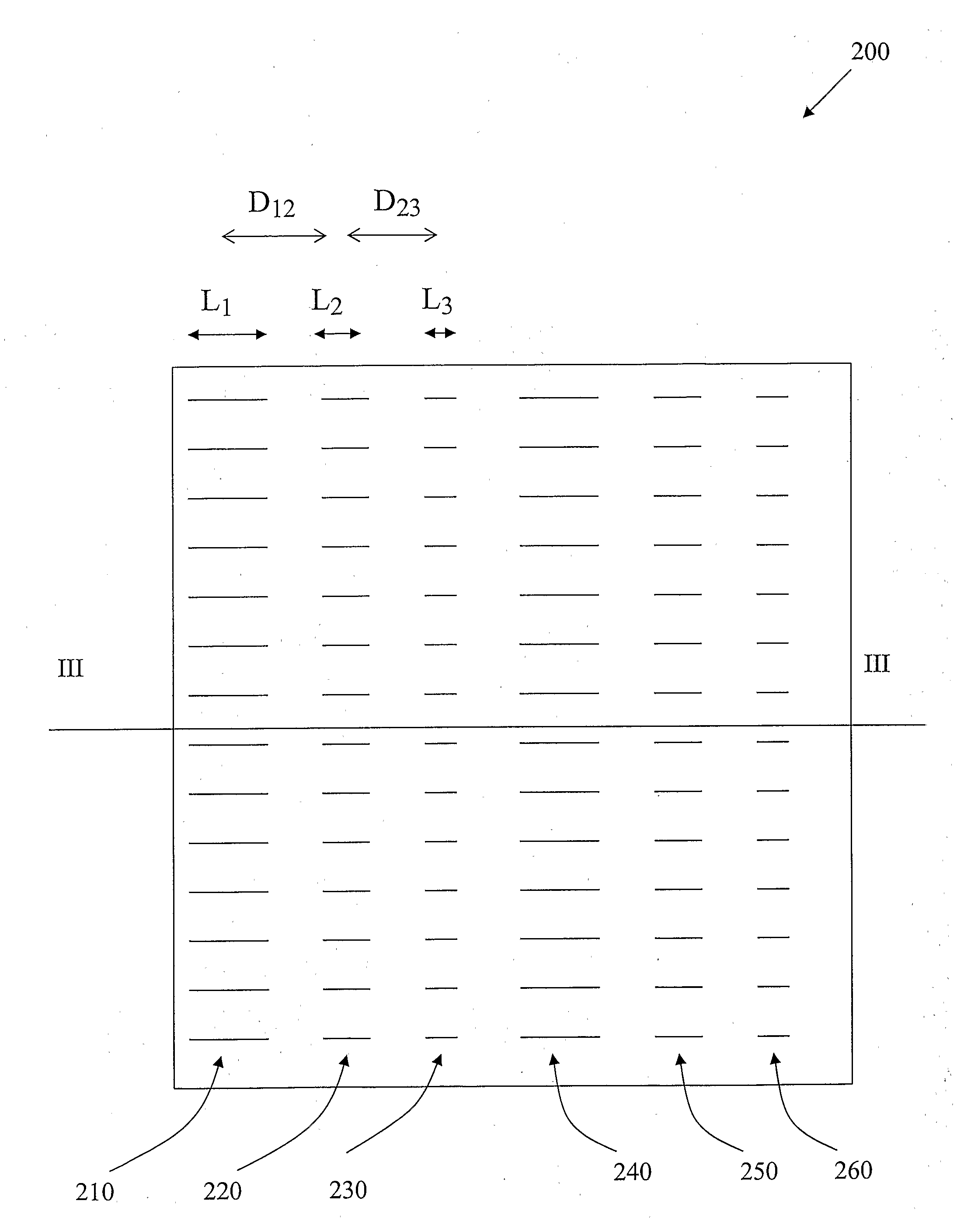
[0017]In FIG. 1, a system 100 which uses the invention is shown schematically. A radio base station (RBS) 105 is intended to cover a cell in a mobile telephony system. Within the cell, there is an area which the RBS 105 cannot cover, either due to a high concentration of users in that area, so that the capacity of the of the RBS isn't sufficient, or due to the fact that the Line Of Sight (LOS) from the RBS to the area is obscured by, for example high-rise buildings. In FIG. 1, the area is shown as being obscured from the RBS by a building 111.

[0018]Naturally, the two factors mentioned can also occur in combination, an area with a high concentration of users can be obscured by buildings or other obstacles.

[0019]As shown in FIG. 1, there is an additional RBS 140, installed on a structure 111 such as a building, in order to help the RBS 105 cover the area in question. This additional RBS 140 can be a so called “micro” or “pico” base station, i.e. a base station with reduced capacity co...


PUM


Abstract

The present invention discloses a repeater antenna comprising a plurality of radiation elements arranged in a first electrically conducting layer or plane. The repeater antenna also comprises a ground plane spaced apart from the radiation elements by a layer of dielectric material, and the radiation elements are each given such an extension (L1, L2, L3) and such a distance (D12, D23) to neighboring radiation elements that an incident electromagnetic wave will reflect from the repeater antenna at an angle (α2) that by a predetermined amount will be greater or smaller than the incident angle (α2) of the electromagnetic wave. The repeater antenna is plane, and can be either curved or flat.

Description

TECHNICAL FIELD[0001]The present invention discloses a passive repeater antenna with a plurality of radiation elements arranged in a first layer or plane, and also comprises a ground plane spaced apart from the radiation elements by a dielectric material.BACKGROUND ART[0002]Operators of wireless systems such as, for example, cellular telephony systems, often wish to increase the capacity of the system in certain areas. In the case of cellular telephony, the operator may wish to increase the system's capacity within certain areas of a cell.[0003]An increase in the system's capacity in a certain area in a cell can be obtained by installing an additional base station to cover that area. Such an additional base station will usually be a so called “micro” or “pico” base station, i.e. a base station with a reduced capacity compared to an ordinary base station, intended to be used to enhance the capacity of an ordinary base station. Naturally, the same effect can also be achieved using an ...

Claims


Application Information

Patent Timeline
IPC IPC(8): H01Q1/38H01Q1/48
CPCH01Q3/46H04B7/145H01Q21/061
Inventor SVENSSON, BENGTSTJERNMAN, ANDERS
Owner TELEFON AB LM ERICSSON (PUBL)
Why Eureka
Try Eureka