Touch Panel

a touch panel and touch technology, applied in the field of touch panels, can solve the problems of poor wearability/durability of the ito layer, uneven resistance over an entire area of the touch panel, and relatively complicated methods

Active Publication Date: 2010-01-07
TSINGHUA UNIV +1
View PDF98 Cites 106 Cited by
  • Summary
  • Abstract
  • Description
  • Claims
  • Application Information

AI Technical Summary

Problems solved by technology

Each of the transparent conductive layers (e.g., ITO layers) is generally formed by means of ion-beam sputtering, and this method is relatively complicated.
Additionally, the ITO layer has poor wearability / durability, low chemical endurance, and uneven resistance over an entire area of the touch panel.
All the above-mentioned problems of the ITO layer make for a touch panel and a liquid crystal display screen with low sensitivity and short lifetime.

Method used


Image

  • Touch Panel
  • Touch Panel
  • Touch Panel

Examples


Embodiment Construction

[0035]Reference will now be made to the drawings to describe, in detail, embodiments of the present touch panel, the liquid crystal display screen using the same, and the methods for making the touch panel and the liquid crystal display screen.

[0036]Touch Panel

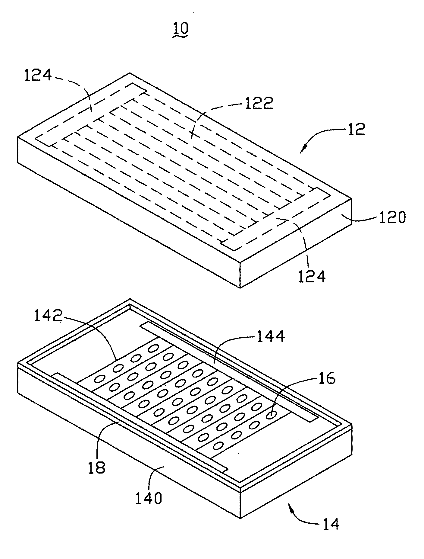
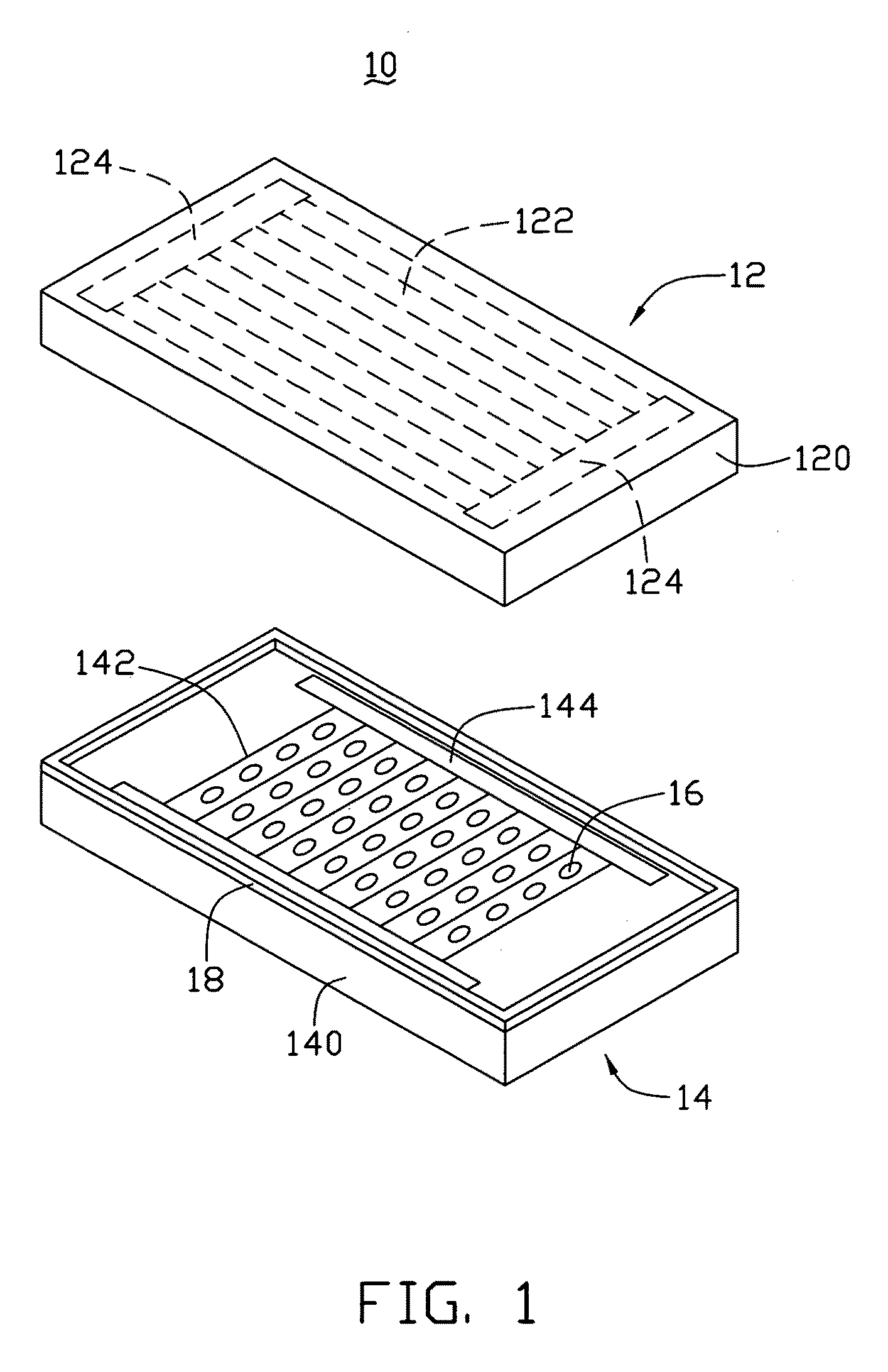
[0037]Referring to FIG. 1 and FIG. 2, a touch panel 10 includes a first electrode plate 12, a second electrode plate 14, and a plurality of dot spacers 16 located between the first electrode plate 12 and the second electrode plate 14.

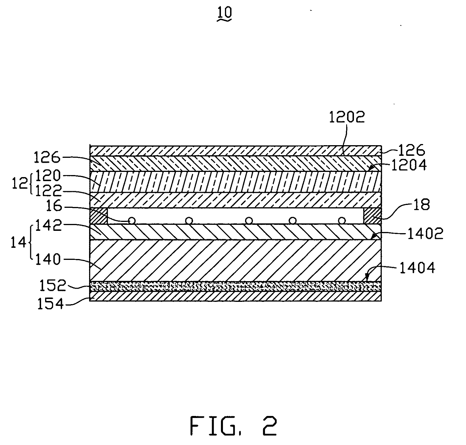
[0038]The first electrode plate 12 includes a first substrate 120, a first conductive layer 122, and two first-electrodes 124. The two first-electrodes 124 and the first conductive layer 122 are located on the second surface 1204 of the first substrate 120. The two first-electrodes 124 can be located on the first conductive layer 122, or the two first-electrodes 124 can be located on the first substrate 120 and electrically connected to the first conductive layer 122. A direction from one of the f...


PUM


Abstract

A touch panel includes a first electrode plate and a second electrode plate connected to the first electrode plated. The first electrode plate includes a first substrate, and a first conductive layer disposed on the first substrate. The second electrode includes a second substrate, and a second conductive layer disposed on the second substrate. The first or the second conductive layer includes at least one carbon nanotube composite layer.

Description

RELATED APPLICATIONS[0001]This application is related to applications entitled, “LIQUID CRYSTAL DISPLAY SCREEN”, filed ______ (Atty. Docket No. US22471); “LIQUID CRYSTAL DISPLAY SCREEN”, filed ______ (Atty. Docket No. US22472); “LIQUID CRYSTAL DISPLAY SCREEN”, filed ______ (Atty. Docket No. US22473); “TOUCH PANEL”, filed ______ (Atty. Docket No. US22474); “METHOD FOR MAKING TOUCH PANEL”, filed ______ (Atty. Docket No. US22475); “TOUCH PANEL AND DISPLAY DEVICE ADOPTING THE SAME”, filed ______ (Atty. Docket No. US22469); “METHOD FOR MAKING LIQUID CRYSTAL DISPLAY SCREEN”, filed ______ (Atty. Docket No. US22476); “METHOD FOR MAKING LIQUID CRYSTAL DISPLAY SCREEN”, filed ______ (Atty. Docket No. US22477); “TOUCH PANEL”, U.S. application Ser. No. 12 / 286,266, filed Sep. 29, 2008; “TOUCH PANEL”, U.S. application Ser. No. 12 / 286,141, filed Sep. 29, 2008; “TOUCH PANEL AND DISPLAY DEVICE USING THE SAME”, U.S. application Ser. No. 12 / 286,189, filed Sep. 29, 2008; “TOUCH PANEL AND DISPLAY DEVICE ...

Claims


Application Information

Patent Timeline
IPC IPC(8): G06F3/041G02F1/1333
CPCB82Y10/00B82Y20/00G02F1/1368G06F3/045Y10T428/269Y10T428/2913H10K30/821
Inventor JIANG, KAI-LILIU, LIANGFAN, SHOU-SHANCHEN, GA-LANECHENG, JIA-SHYONGWU, JEAH-SHENG
Owner TSINGHUA UNIV
Why Eureka
Try Eureka