Tire For Construction Vehicle
- Summary
- Abstract
- Description
- Claims
- Application Information
AI Technical Summary
Benefits of technology
Problems solved by technology
Method used
Image

Examples
first embodiment
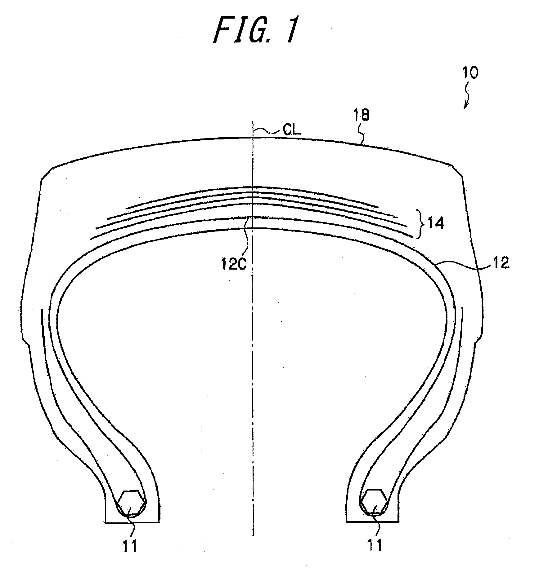
[0059]To begin with, a first embodiment of the present invention will be described below. As shown in FIG. 1, a construction vehicle tire 10 of the first embodiment includes a carcass 12 having both edges folded around the respective bead cores 11. The carcass 12 is comprised of a single or plural carcass plies.
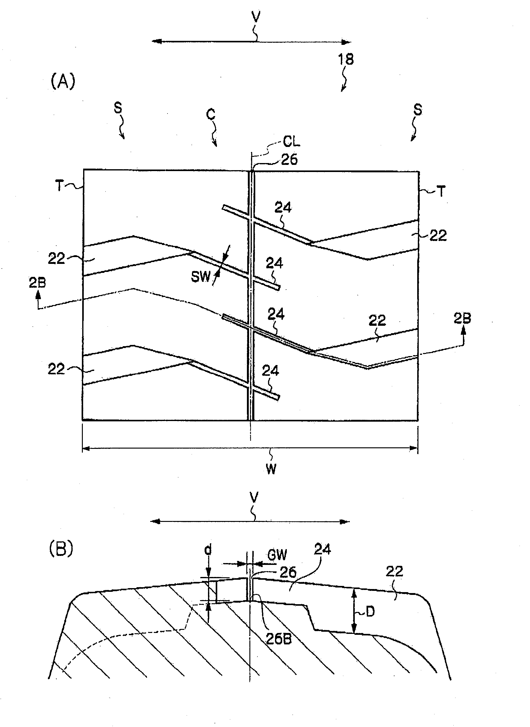
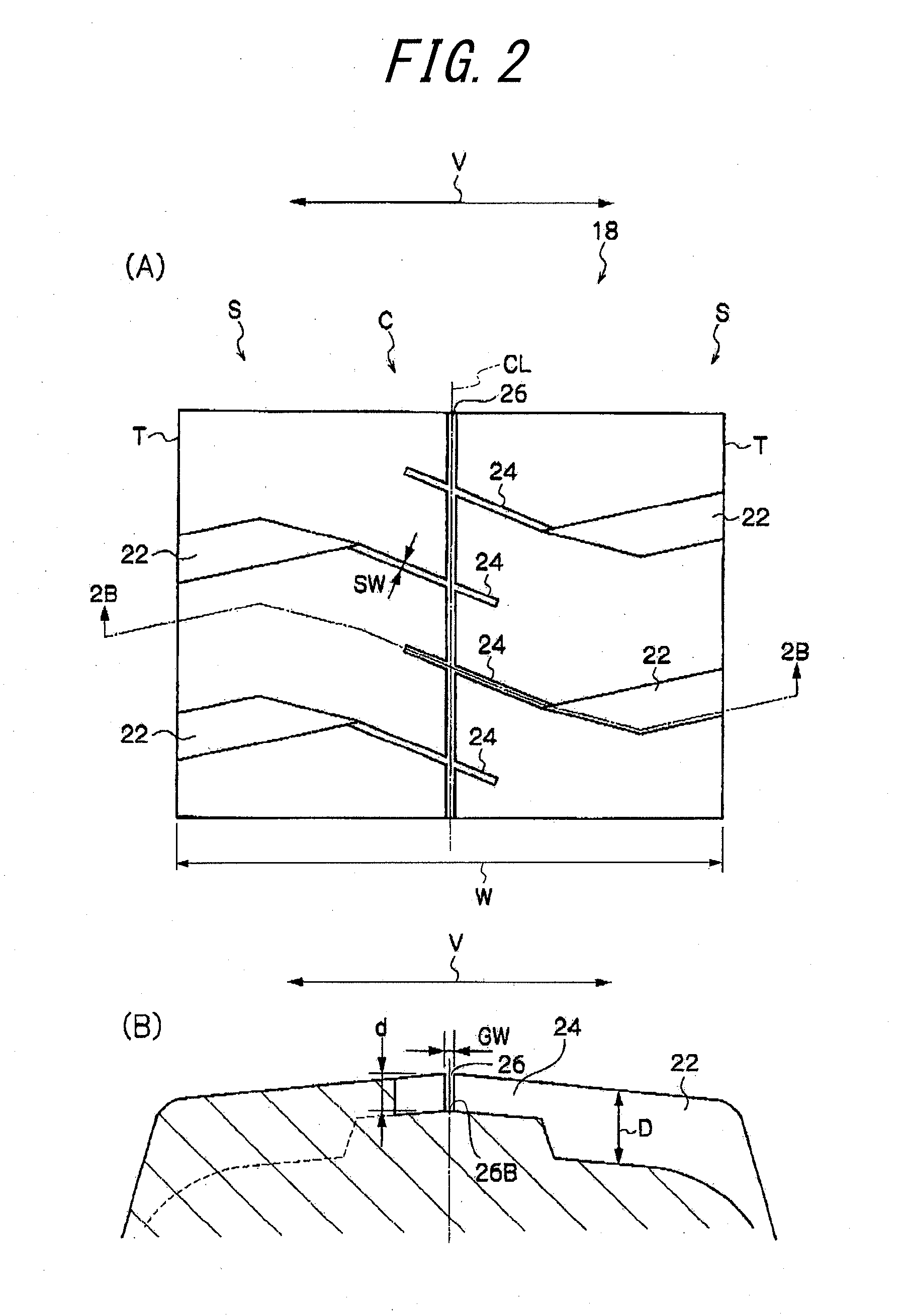
[0060]On the radially outer side of the crown portion 12C of the carcass 12, there is embedded a belt 14 comprised of a plurality of belt layers, which are superimposed one above the other. On the radially outer side of the carcass 12, as shown in FIG. 1 and FIGS. 2(A) and 2(B), there is formed a tread portion 18 in which grooves are arranged. As the rubber forming the tread rubber, there is used a rubber having predetermined properties.
[0061]A plurality of lug grooves 22 are formed in the tread shoulder regions S on both sides in the tire width direction.
[0062]In the tire center portion C, a plurality of narrow widthwise grooves 24 are arranged so as to extend substantially ...
second embodiment
[0073]A second embodiment of the present invention will be described below. In the construction vehicle tire according to the second embodiment, as compared to the first embodiment, instead of the narrow widthwise grooves 24, narrow widthwise grooves 28 as shown in FIG. 3 are formed in the tread portion 30.
[0074]Each narrow widthwise groove 28 has both ends connected to the lug grooves 22, and extends in the tire center portion C substantially along the tire width direction. The position of the lug grooves 22 is changed in order that the both ends of the narrow widthwise groove 28 can be connected to the lug grooves 22 in the manner described above.
[0075]According to the second embodiment, it is possible to provide a further enhanced heat radiation effect in the tire center portion, a higher stiffness of the land portion and an improved wear resistance.
third embodiment
[0076]A third embodiment of the present invention will be described below. In the construction vehicle tire according to the third embodiment, as compared to the first embodiment, instead of the narrow widthwise grooves 24, narrow widthwise grooves 34 as shown in FIG. 4 are formed in the tread portion 32.
[0077]The narrow widthwise grooves 34 are arranged in the tire center portion C and extend substantially along the tire width direction. Each narrow widthwise grooves 34 intersects with the deep equatorial groove 26, and has its both ends terminating in the tread without opening into the lug grooves 22.
[0078]Such an arrangement makes it possible to realize a construction vehicle tire highly effectively satisfying user's requirement for a large traction force. This is because if a large traction force acts on a tire, wherein the narrow widthwise grooves are connected to the lug grooves, as in the first embodiment, the narrow widthwise grooves and the lug grooves tend to exhibit diffe...
PUM
 Abstract
Description
Claims
Application Information
 - Generate Ideas
- Intellectual Property
- Life Sciences
- Materials
- Tech Scout
- Unparalleled Data Quality
- Higher Quality Content
- 60% Fewer Hallucinations
Browse by: Latest US Patents, China's latest patents, Technical Efficacy Thesaurus, Application Domain, Technology Topic, Popular Technical Reports.
© 2025 PatSnap. All rights reserved.Legal|Privacy policy|Modern Slavery Act Transparency Statement|Sitemap|About US| Contact US: help@patsnap.com