Gas absorption reservoir with optimized cooling

a technology of gas absorption reservoir and optimized cooling, which is applied in the direction of transportation items, packaging goods, containers preventing decay, etc., can solve the problem of considerable energy expenditur

Active Publication Date: 2010-01-14
ROBERT BOSCH GMBH 50 +1
View PDF9 Cites 18 Cited by
  • Summary
  • Abstract
  • Description
  • Claims
  • Application Information

AI Technical Summary

Benefits of technology

[0021]According to the invention, this object is attained in that the physical effect of cooling from adiabatic expansion with the physical effect of heating of the tank from sorption, such as physical adsorption in the case of MOF, is compensated for by the installed position of a throttle valve on the filling side of the tank for gaseous fuel. By the use of MOF in a tank for receiving gaseous fuel, the pressure level when the tank is being filled can moreover advantageously be lowered to a considerably lower pressure level. This pressure level is below 100 bar; it is preferably <80 bar and especially preferably <50 bar, but is above 10 bar. Natural gas or city gas is preferably used as the gaseous fuel.

Problems solved by technology

Such gas pumps require an upstream compressor in order to offer this pressure, which involves a considerable expenditure of energy in order to maintain the pressure level of about 10 bar.

Method used


Image

  • Gas absorption reservoir with optimized cooling
  • Gas absorption reservoir with optimized cooling
  • Gas absorption reservoir with optimized cooling

Examples


Embodiment Construction

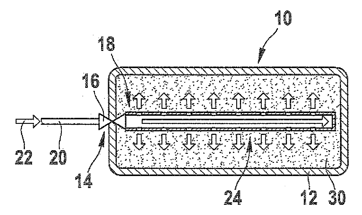
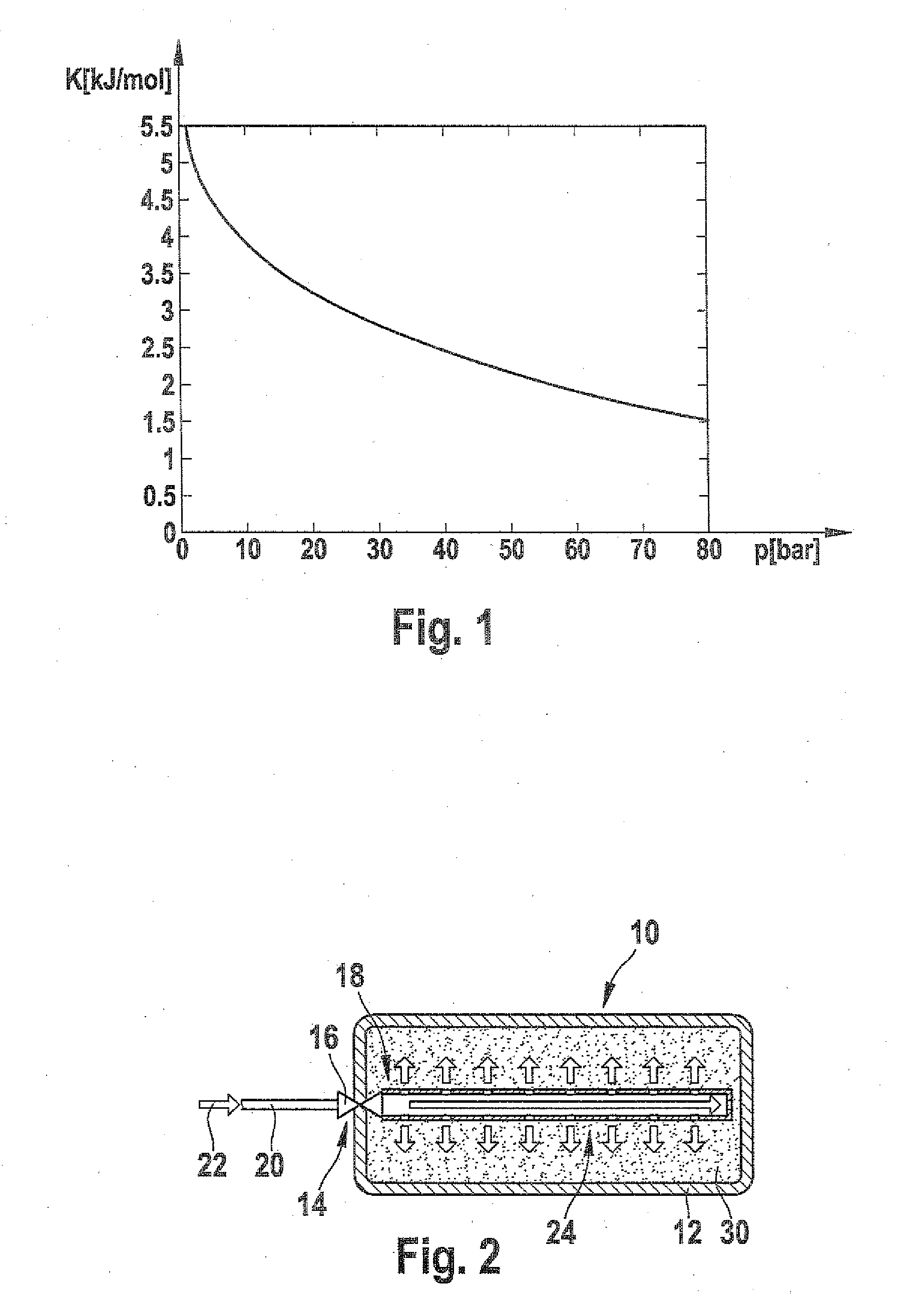
[0032]From the diagram in FIG. 1, the course of the cooling energy for CH4 can be seen, where κ=1.33, a filling pressure p1 is 200 bar, and a temperature of T=25° C.

[0033]It can be seen from FIG. 1 that the utilizable cooling energy K, for a virtually completely empty tank, assumes its maximum value for receiving a gaseous fuel, such as CH4. During the tank filling process, the cooling energy K, as shown by the course of the curve in FIG. 1, decreases steadily with increasing filling of the tank for gaseous fuel, such as CH4, and at a reservoir pressure p of 50 bar, for instance, it assumes a value of approximately 2.25 kJ / mol. The course shown in FIG. 1 of the cooling energy K from adiabatic expansion, at an outset pressure of p1, is utilized by the version proposed according to the invention compensation of the in the accumulation of gaseous fuel on an accumulation structure, preferably embodied as an MOF structure, contained in the tank for gaseous fuel.

[0034]The term tank will b...


PUM

PropertyMeasurementUnit
pressureaaaaaaaaaa
pressureaaaaaaaaaa
massaaaaaaaaaa

Abstract

The invention relates to a fuel reservoir for gaseous fuel in a vehicle, in particular a sorption reservoir. The fuel reservoir is delimited by at least one wall and includes a sorption material that is contained in its interior. The fuel reservoir has a tank inlet valve containing a shut-off valve and a throttle restriction valve. The restriction of the gaseous fuel takes place inside the fuel reservoir.

Description

PRIOR ART[0001]As an alternative to liquid fuels, gaseous fuels can be used, which differ from fuels that are in liquid form in having a lower energy density. Because of their lower energy density, gaseous fuels in motor vehicles or in buses or utility vehicles for local or long-distance travel are stored in pressure reservoirs. Inside such a pressure reservoir, the pressure level is on the order of magnitude of about 200 bar. The tanks of compressed-gas-powered vehicles are filled at filling stations that have gas pumps equipped especially for filling the tanks of compressed-gas-powered vehicles, which make the gaseous fuel available at a pressure of more than 200 bar. Such gas pumps require an upstream compressor in order to offer this pressure, which involves a considerable expenditure of energy in order to maintain the pressure level of about 10 bar.[0002]From U.S. Pat. No. 6,591,616 B2, an infrastructure for storing hydrogen for a hydrogen-fueled vehicle is known. Hydrogen is c...

Claims


Application Information

Patent Timeline
Patent Type & Authority Applications(United States)
IPC IPC(8): F17C11/00
CPCF17C11/007Y10T137/0318Y10T137/7764Y10T137/7837
Inventor GRUENWALD, WERNERALLGEIER, THORSTENOERTEL, KAIFAYE, IANLEUTHNER, STEPHANGRAEHN, JAN-MICHAELSCHUBERT, MARKUS
Owner ROBERT BOSCH GMBH 50
Why Eureka
Try Eureka