Collecting container, in particular for collecting packages

Active Publication Date: 2010-01-14
DEUTSCHE POST
View PDF14 Cites 14 Cited by
  • Summary
  • Abstract
  • Description
  • Claims
  • Application Information

AI Technical Summary

Benefits of technology

[0022]Thus, in this upper position, the catching device is preferably positioned at a height in which the dropped-in objects can be caught as soon as possible. Since the catching device is lowered because of the weight of the objects collecting on it, additional objects can then be inserted. These, however, do not fall all the way to the bottom of the container, but rather, are likewise caught by the catching device at the highest possible level. The catching device thus constitutes a gravity brake and prevents packages from falling from a considerable height and being damaged. The catching device also reduces the

Problems solved by technology

The containers are normally characterized in that the receiving device is configured in such a way that, when used clothing is dropped into the container, the receiving device does not allow access to objects that have already been placed into the container.
When it comes to mailboxes, the insertion slot is normally configured to be so narrow that it is not possible to access the mail that has already been dropped in.
Here, the flap is configured in such a manner that, when it is open, it does not allow access to the packages that have already been dropped into the storage space.
With the collecting containers known from the state of the art, it can happen that a user still tries to i

Method used


Image

  • Collecting container, in particular for collecting packages
  • Collecting container, in particular for collecting packages
  • Collecting container, in particular for collecting packages

Examples


Example

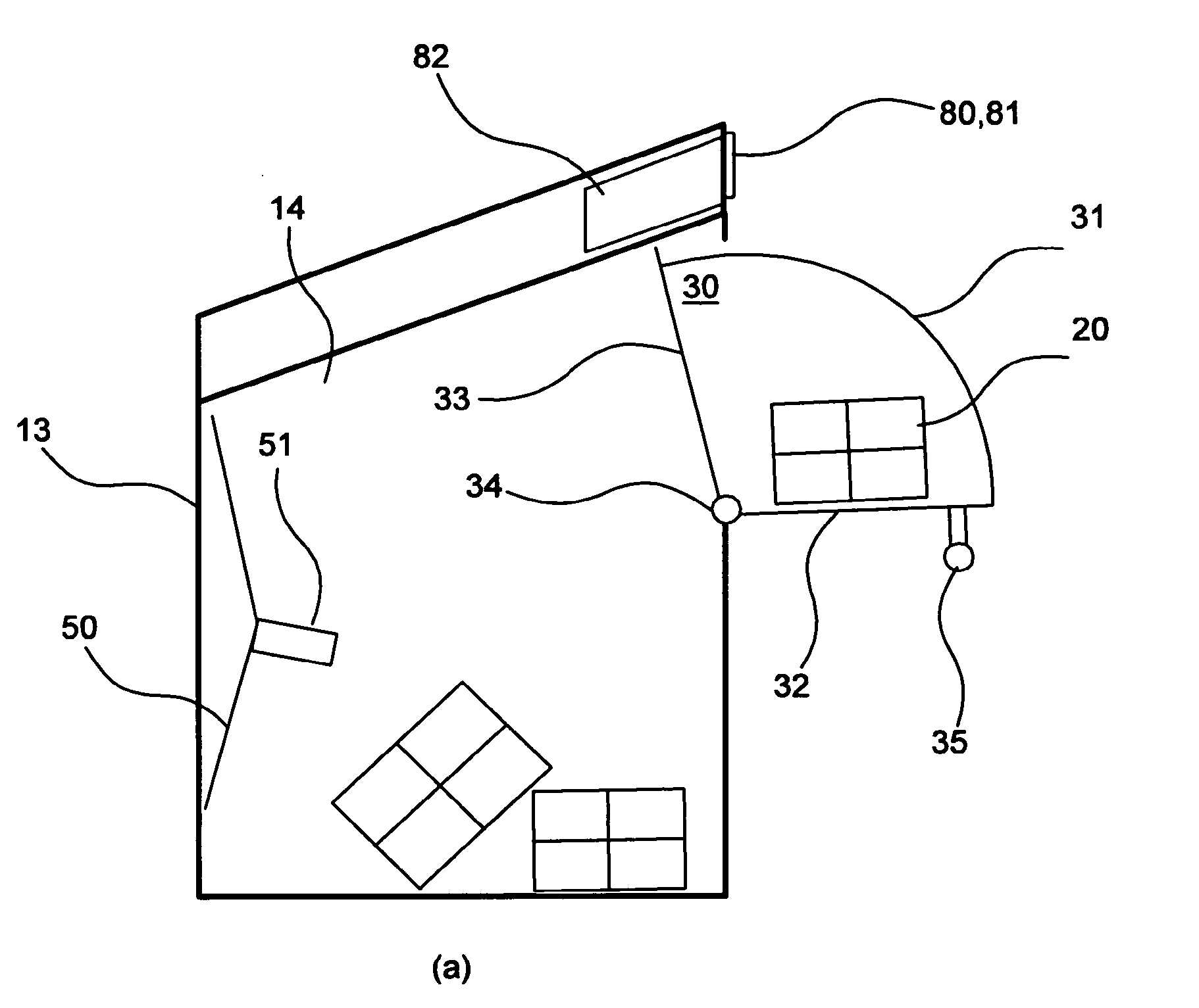
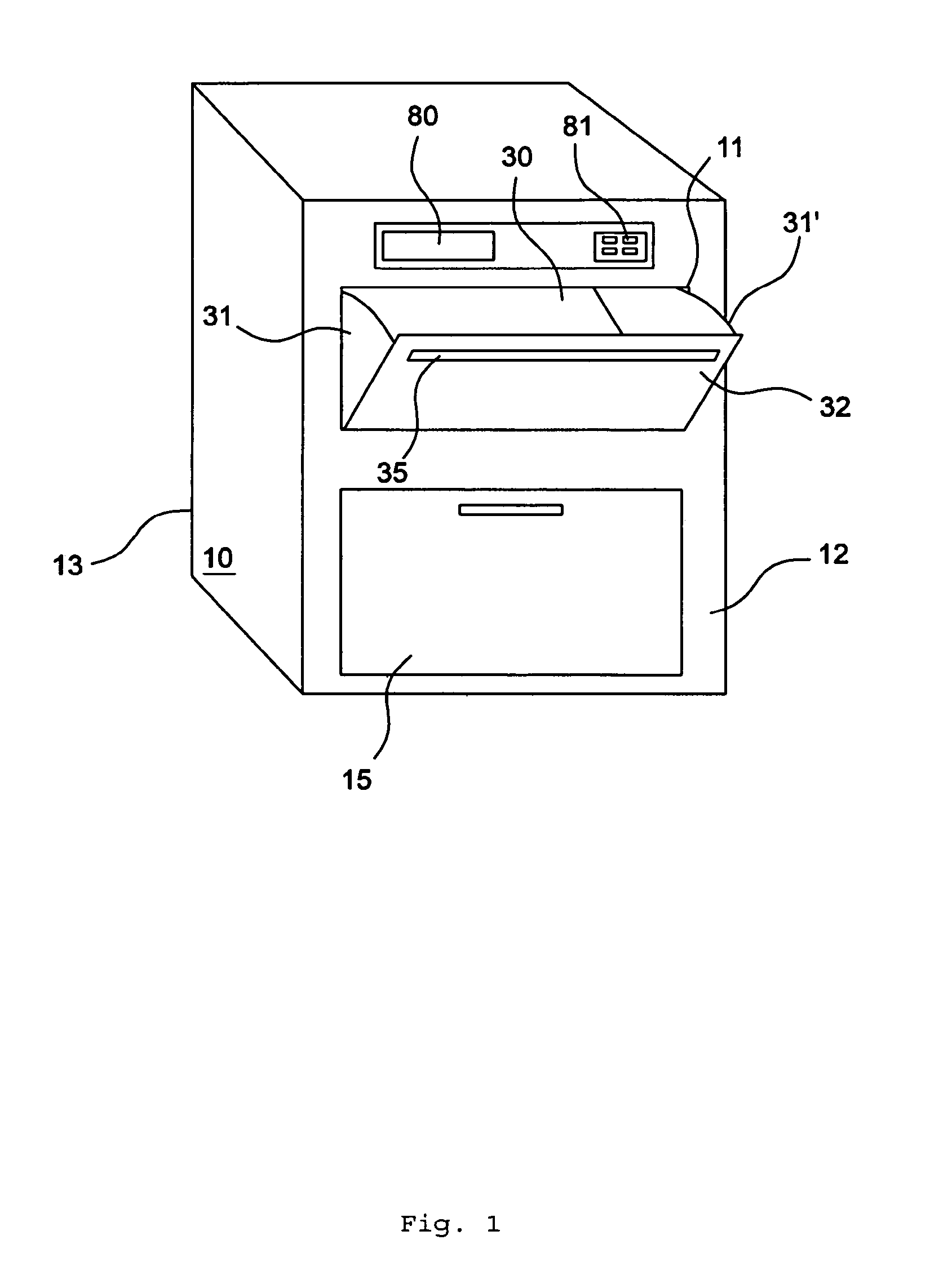
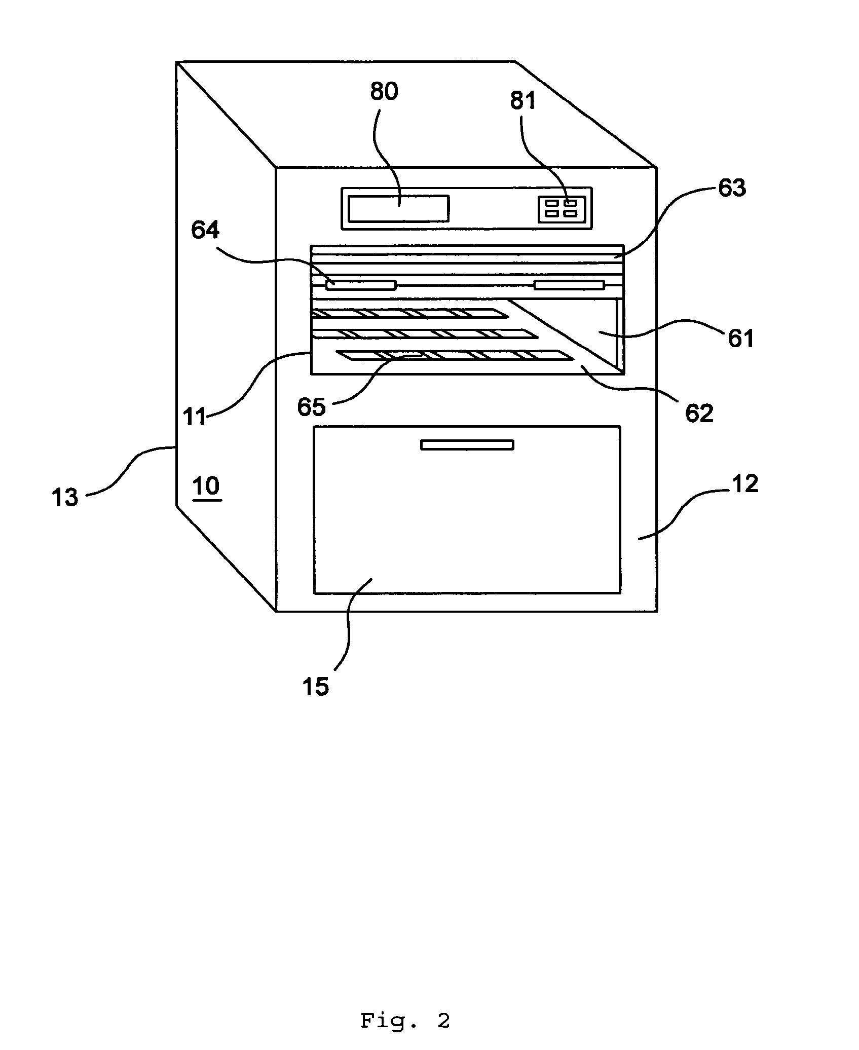
[0037]A collecting container according to an exemplary embodiment of the present invention may comprise an insertion opening on the front of the collecting container so that objects can be dropped in. The collecting container also has a removal opening for emptying the container. Inside the insertion opening, there is a receiving device that receives the objects and conveys them to a storage space in the collecting container. This receiving device can be moved between at least two operating states, in a first operating state, the receiving device allowing an object to be received in it, whereas the entrance from the receiving device to the storage space is blocked. In a second operating state of the receiving device, an object cannot be received in it, whereas the entrance from the receiving device to the storage space is open.

[0038]The collecting container according to an exemplary embodiment of the present invention will be described below with reference to several embodiments. Pa...


PUM


Abstract

There is provided a collecting container. An exemplary collecting container comprises an insertion opening on the front of the collecting container that is adapted to receive objects that are dropped in and a removal opening, inside the insertion opening. The exemplary collecting container additionally comprises a receiving device arranged to receive the objects and to convey them to a storage space in the collecting container, the receiving device being movable between at least two operating states, a first operating state in which the receiving device allows an object to be received in it, while the entrance from the receiving device to the storage space is blocked, and a second operating state in which the receiving device does not allow an object to be received in it, while the entrance from the receiving device to the storage space is open, the storage space containing a filling-level measuring means that is connected to a blocking device preventing the receiving device from being opened when a defined filling level has been reached in the storage space, the receiving device comprising a roller shutter box whose receiving area is formed by at least two side walls and a bottom. The exemplary collecting container further comprises a roller shutter that is adapted to be moved in rails on the side walls in such a way that, in a first position, the roller shutter covers the entrance from the receiving area of the roller shutter box to the storage space, while the receiving area of the roller shutter box is accessible to the user and, in a second position, the roller shutter covers the insertion opening, while the entrance from the receiving area of the roller shutter box to the storage space is open, the blocking device being configured so that it can block the movement of the roller shutter.

Description

CROSS REFERENCE TO RELATED APPLICATIONS[0001]Pursuant to 35 U.S.C. § 371, this application is the United States National Stage Application of International Patent Application No. PCT / EP2007 / 007171, filed on Aug. 14, 2007, the contents of which are incorporated by reference as if set forth in their entirety herein, which claims priority to German (DE) Patent Application No. 10 2006 039 002.4, filed Aug. 21, 2006, the contents of which are incorporated by reference as if set forth in their entirety herein.BACKGROUND[0002]An exemplary embodiment of the present invention relates to a collecting container.[0003]Known collecting containers may be adapted to collect used clothing. The containers are normally characterized in that the receiving device is configured in such a way that, when used clothing is dropped into the container, the receiving device does not allow access to objects that have already been placed into the container. A collecting container of this type is disclosed, for e...

Claims


Application Information

Patent Timeline
IPC IPC(8): B65G11/20B65G11/00
CPCA47G29/22A47G29/122
Inventor FRANKENBERG, STEFFENRASS, MARTINBENZ, RAMINHEIN, SVENPAUL, BORIS
Owner DEUTSCHE POST
Why Eureka
Try Eureka