Gain Control for Linear Radio Freqency Power Amplifiers

a technology of gain control and linear radio frequency, applied in the direction of amplifiers, gain control, electrical equipment, etc., can solve the problems of linear pas gain increasing, unobservable effect, and not the cas

Active Publication Date: 2010-01-14
SIGE SEMICON
View PDF5 Cites 53 Cited by
  • Summary
  • Abstract
  • Description
  • Claims
  • Application Information

AI Technical Summary

Benefits of technology

[0010]an output port electrically coupled to the electronic circuitry, the output port for being electrically

Problems solved by technology

Unfortunately, the gain of linear PAs tends to increase with increasing supply voltage because the increased supply voltage causes an improvement to the high frequency performance of the underlying semiconductor transistors forming amplification stages within the PA.
In most stationary applications of WLAN systems the supply voltage to the PA is sufficiently stable during the burs

Method used


Image

  • Gain Control for Linear Radio Freqency Power Amplifiers
  • Gain Control for Linear Radio Freqency Power Amplifiers
  • Gain Control for Linear Radio Freqency Power Amplifiers

Examples


Embodiment Construction

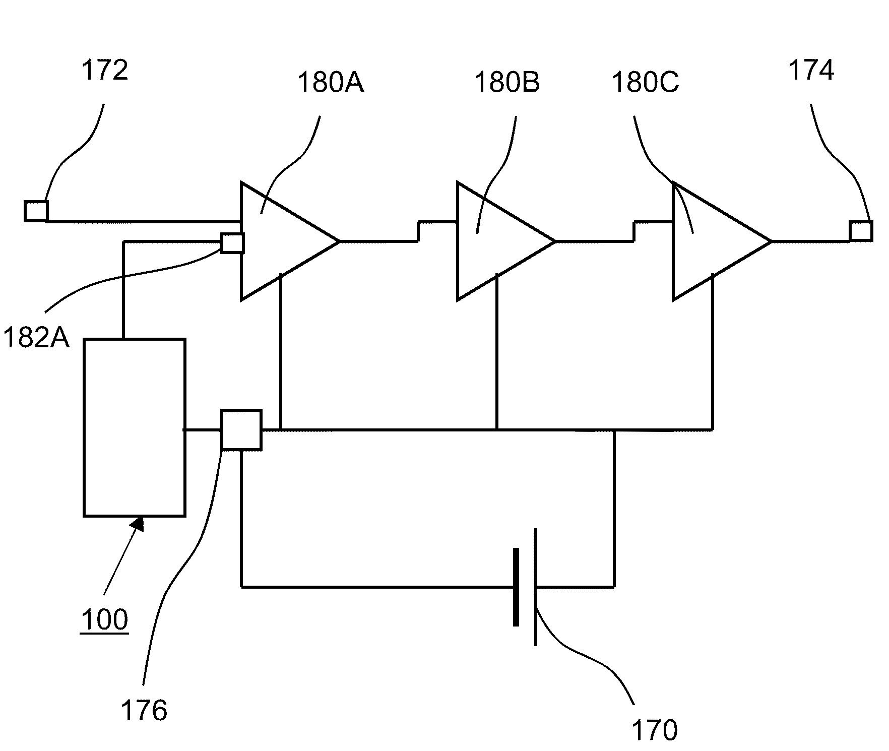
[0007]In accordance with an aspect of the present invention there is provided a bias control circuit comprising:[0008]an input port for receiving a signal indicative of an amplitude of a supply voltage, the supply voltage for being provided to a multi stage power amplifier circuit;[0009]electronic circuitry electrically coupled to the input port, the electronic circuitry for generating, in dependence upon the signal indicative of a supply voltage, a bias control signal for provision to a first stage power amplifier of the multi stage power amplifier circuit, the bias control signal being generated such that a gain change of the multi stage power amplifier circuit due to a supply voltage change is substantially compensated; and,[0010]an output port electrically coupled to the electronic circuitry, the output port for being electrically coupled to a bias port of the first stage power amplifier and for providing the bias control signal thereto.

[0011]In accordance with an aspect of the ...


PUM


Abstract

A bias control circuit is provided comprising an input port for receiving a signal indicative of an amplitude of a supply voltage provided to a multi stage power amplifier circuit. Electronic circuitry, electrically coupled to the input port, generates a bias control signal in dependence upon the signal indicative of a supply voltage for provision to a first stage power amplifier of the multi stage power amplifier circuit. The bias control signal is generated such that a gain change of the multi stage power amplifier circuit due to a supply voltage change is substantially compensated.

Description

CROSS-REFERENCE TO RELATED APPLICATION[0001]This application claims the benefit of U.S. Provisional Patent Application No. 61 / 078,979 filed on Jul. 8, 2008, the entire contents of which are incorporated herein by reference.FIELD OF THE INVENTION[0002]The instant invention relates to the field of power amplifier circuits and in particular to a constant gain control for linear radio frequency power amplifiers.BACKGROUND[0003]Wireless Local Area Network (WLAN) technology is becoming widely used in home, office, and in mobile applications. In WLAN systems, modulation techniques such as, for example, 64 Quadrature Amplitude Modulation (QAM) Orthogonal Frequency Division Multiplexing (OFDM) in WLAN 802.11g systems are used for the data transmission. In order for the modulation technique to function reliably, the gain and phase of a Power Amplifier (PA) within the transmitter needs to be substantially linear. A proxy for linearity is Error Vector Magnitude (EVM) expressed in percentage ter...

Claims


Application Information

Patent Timeline
IPC IPC(8): H03G3/20
CPCH03G3/007H03F1/30H03F1/0261H03G3/3047
Inventor SEARLE, KENNETHWHITTAKER, EDWARD J.
Owner SIGE SEMICON
Why Eureka
Try Eureka