Method of object location in airborne imagery using recursive quad space image processing

Active Publication Date: 2010-01-14
THE BF GOODRICH CO
View PDF31 Cites 12 Cited by
  • Summary
  • Abstract
  • Description
  • Claims
  • Application Information

AI Technical Summary

Benefits of technology

[0031]In the above embodiments, the workstation provides a display of the oblique image and allows an operator to select any arbitrary point in the image, and the display indicates the longitude and latitude of the selected point with greater accuracy than previous methods that are based on linear interpolation. Furthermore, the method and workstation are readily adaptable to perform the methods on any oblique digital image, from any suitable reconnai

Problems solved by technology

While this method gives satisfactory results for imagery captured vertically or perpendicular (at nadir) to the platform, it produces significant error when imagery is captured at angles forward oblique or side oblique relative to the platform.
This error is due to the progressive scaling characteristics intrinsic to oblique images, and the application of linear interpolation techniques introduces approximation errors along the vanishing lines.
The error produced by using linear interpolation to geo-locate objects in oblique imagery stems from the fact that the field of view (FOV) of an obliquely captured image can be described as having a trapezoidal shape relative to the ground, when defined by the far and near corner points.
As the angle of capture relative to the platform nadir increases (

Method used


Image

  • Method of object location in airborne imagery using recursive quad space image processing
  • Method of object location in airborne imagery using recursive quad space image processing
  • Method of object location in airborne imagery using recursive quad space image processing

Examples


example embodiment

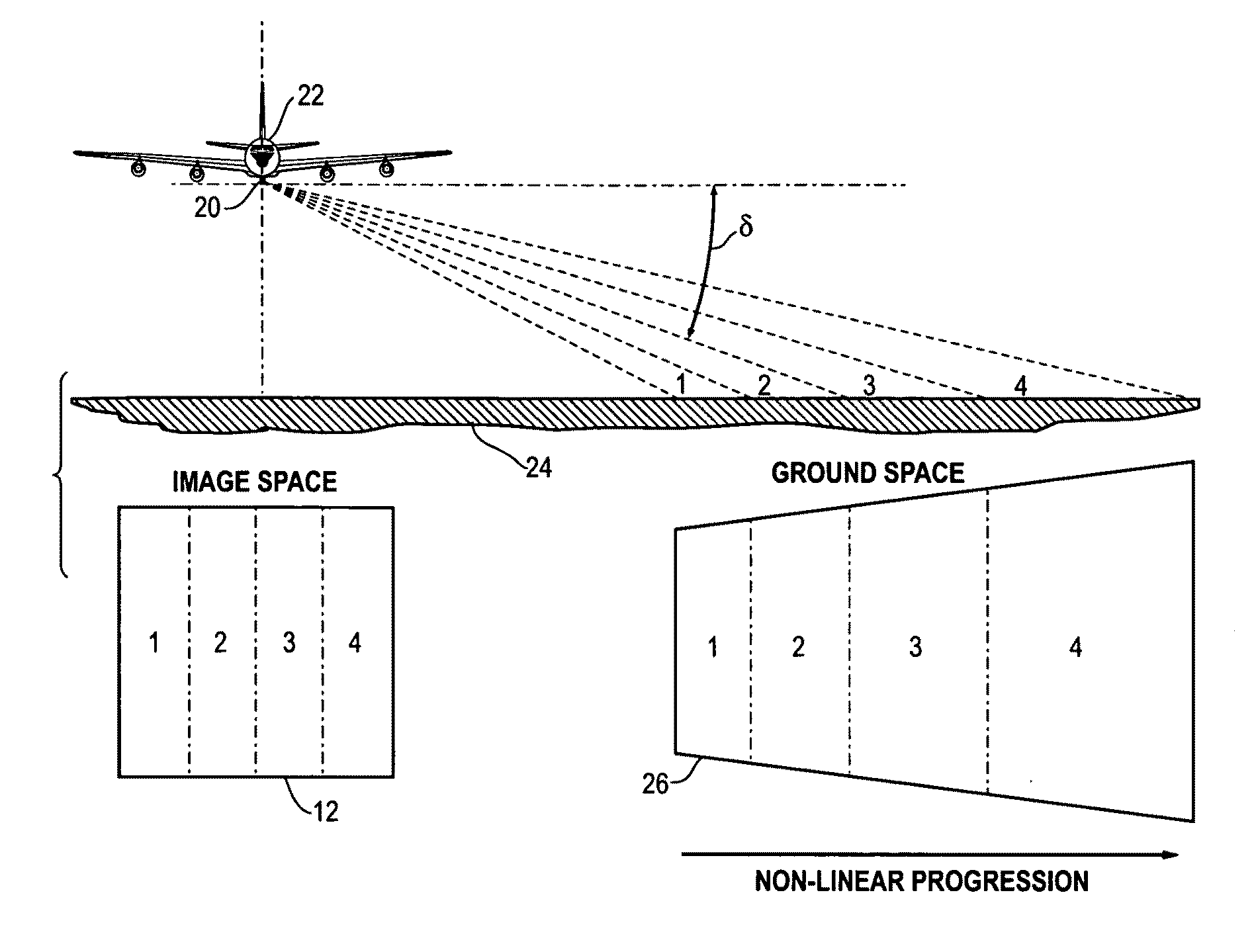
[0047]The method will now be described in conjunction with the appended figures. The method will be described in the context of a side oblique image; however, the method is applicable to a nadir image and any oblique image, including an image obtained in the forward oblique. The nature of the image (e.g., thermal, visible, hyperspectral, etc.) and the nature of aerial reconnaissance camera are not particularly important. The term “aerial reconnaissance image” is intended to encompass an image obtained from an airborne camera or from an orbiting satellite.

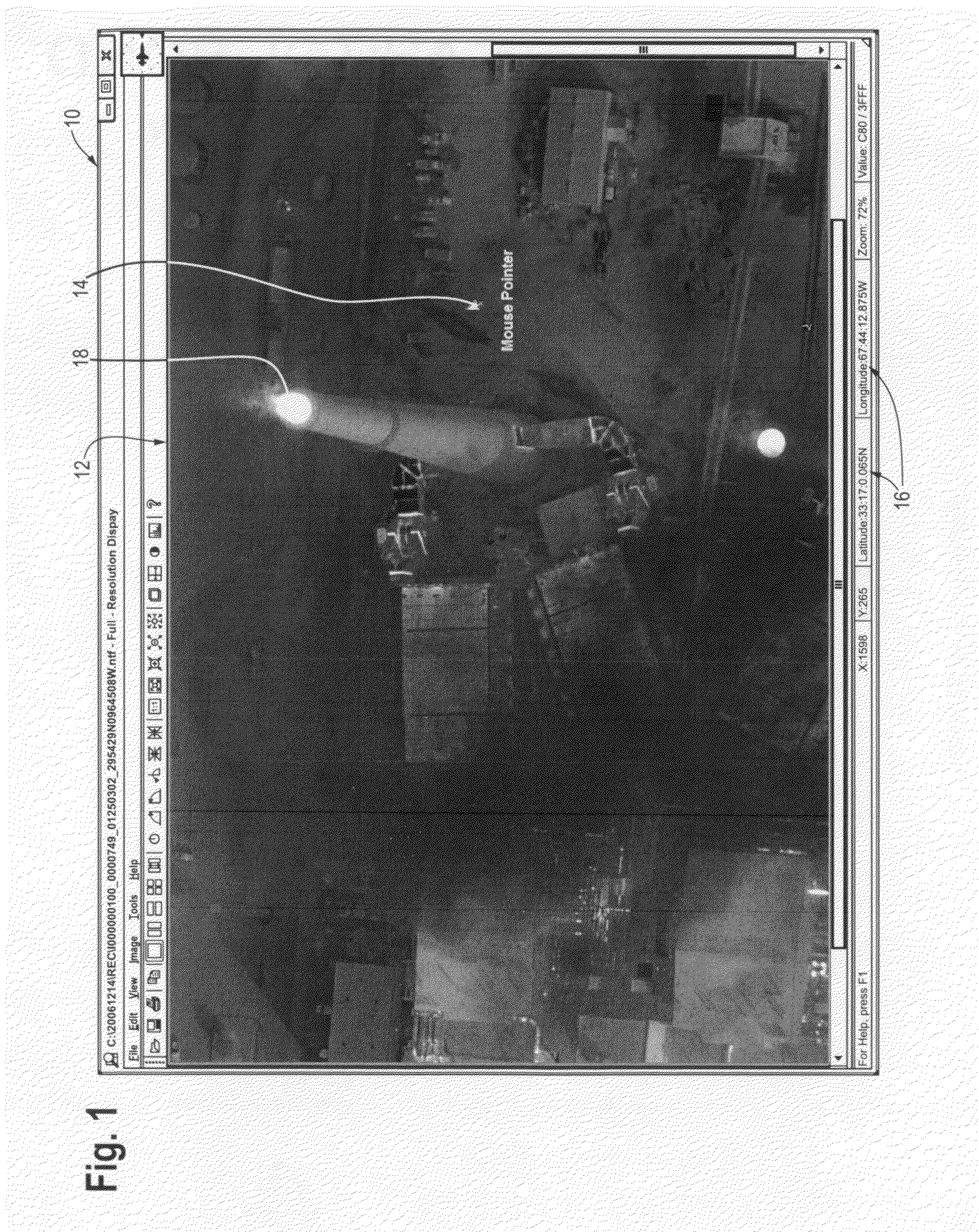
[0048]FIG. 1 is a screen shot of the display 10 of an image exploitation station (computer workstation) showing an oblique image 12 of the earth generated by an aerial reconnaissance camera. The user moves cursor 14 with a mouse or other pointing device to any arbitrary point in the image. The method of this invention calculates the longitude and latitude of the selected point in the image and displays it as indicated at 16. For exa...


PUM


Abstract

A method and computer workstation are disclosed which determine the location in the ground space of selected point in a digital image of the earth obtained by an airborne camera. The image is rectangular and has four corners and corresponds to an image space. The image is associated with data indicating the geo-location coordinates for the points in the ground space corresponding to the four corners of the image, e.g., an image formatted in accordance with the NITF standard. The method includes the steps of: (a) performing independently and in parallel a recursive partitioning of the image space and the ground space into successively smaller quadrants until a pixel coordinate in the image assigned to the selected point is within a predetermined limit (Δ) of the center of a final recursively partitioned quadrant in the image space. The method further includes a step of (b) calculating a geo-location of the point in the ground space corresponding to the selected point in the image space from the final recursively partitioned quadrant in the ground space corresponding to the final recursively partitioned quadrant in the image space. The methods are particularly useful for geo-location from oblique reconnaissance imagery.

Description

BACKGROUND OF THE INVENTION[0001]This invention relates generally to the fields of aerial surveillance and mapping from aerial photography. In particular, the invention relates to a method of determining the geo-location (e.g., longitude and latitude coordinates) of any arbitrary point in a photograph of the Earth's surface taken by a digital camera in an airborne vehicle or satellite. The method is particularly useful for geo-location from oblique imagery.[0002]The known prior art includes several references related to the problem of locating coordinates of a selected point on the ground within imagery obtained from an airborne camera. The prior art of interest includes U.S. Pat. No. 6,735,348 to Dial, Jr. et al.; U.S. Pat. No. 5,633,946 to Lachinski et al., U.S. Pat. No. 7,233,691 to Setterholm; and U.S. Pat. No. 5,596,494 to Kuo.[0003]Prior art methodologies typically accomplish the task by calculating the location of the airborne platform using the onboard inertial navigation sy...

Claims


Application Information

Patent Timeline
IPC IPC(8): G06K9/00
CPCG06T3/00B64G1/1021G06T17/05G06V10/24
Inventor CHIEN, GREG T.H.
Owner THE BF GOODRICH CO
Why Eureka
Try Eureka