Cleaning device and image forming apparatus

a technology of cleaning device and image bearing member, which is applied in the direction of optics, instruments, electrographic processes, etc., can solve the problems of image bearing member cleaning failur

Inactive Publication Date: 2010-01-14
RICOH KK
View PDF13 Cites 39 Cited by
  • Summary
  • Abstract
  • Description
  • Claims
  • Application Information

AI Technical Summary

Benefits of technology

[0054]The cleaning device of the present invention uses a brush roller having brush fibers each containing a conductive agent dispersed homogeneously therein or dispersed only in a surface layer thereof, and another brush roller having oblique brush fibers each containing a conductive agent localized in a center portion thereof, the oblique brush fibers being obliquely provided so that tip portions thereof are curled on an image bearing member in a direction in which the image bearing me

Problems solved by technology

But, if the similar phenomenon arises in downstream cleaning brush fibers, the toner particles which have adher

Method used


Image

  • Cleaning device and image forming apparatus
  • Cleaning device and image forming apparatus
  • Cleaning device and image forming apparatus

Examples


example 1

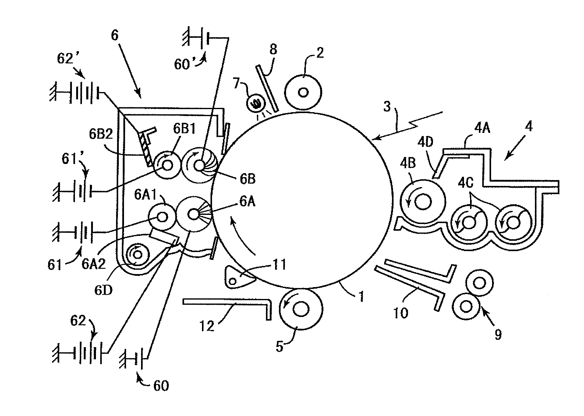
[0212]In this Example, there is used an image forming apparatus shown in FIG. 1 whose second brush roller 6B has obliquely provided brush fibers (shown in FIG. 15A) with a sheath structure shown in FIG. 9 or 10.

[0213]Next will be given specific information concerning some constituent members of the cleaning device. The specific information will be described in a manner similar to that employed above in relation to the experiment using the image forming apparatus shown in FIG. 19.

First Brush Roller 6A:

[0214]Material: conductive polyester

[0215]Backing width: 5 mm

[0216]Brush fiber height: 3 mm

[0217]Conductive agent: homogeneously dispersed in a surface (FIG. 8)

[0218]Arrangement of brush fibers: upright provided

[0219]Diameter of the brush roller: 14 mm

[0220]Resistance of brush original yarn: 108 Ω·cm

[0221]Brush fiber density: 100,000 / inch2 (1 inch=0.0254 m)

[0222]Intrusion amount with respect to photoconductor drum: 1 mm

Recovering Roller 6A1:

[0223]Material: metal core: SUS

[0224]Intermedi...

example 2

[0262]In Example 2, there is used an image forming apparatus whose second brush roller 6B, which is disposed downstream of the first brush roller in a direction in which the photoconductor drum 1 is moved, has looped brush fibers as shown in FIG. 15B.

[0263]FIG. 21 is an enlarged view of the looped brush fibers of the second brush roller (for the sake of convenience, each looped brush fiber is denoted by reference character 6B′).

[0264]In the image forming apparatus shown in FIG. 1, the second brush roller 6B has obliquely provided brush fibers which come into contact with the photoconductor as shown in FIG. 15A. But, as time passes, the brush fibers change in form from the initial state, potentially resulting in that they come into contact with remaining toner particles as shown in FIG. 11. In view of this, even after change in form over time, the brush fibers are looped, preventing the conductive agent from coming into contact with toner particles.

[0265]In the looped brush fibers, t...

example 3

[0284]The configuration of this Example is characterized in that the metal core of the recovering roller is connected to the ground.

[0285]FIG. 22 is an enlarged view of the recovering roller 6A1 which is in contact with the first brush roller 6A. In this figure, the metal core of the recovering roller 6A1 is not given a voltage but connected to the ground.

[0286]Here, voltages applied to members are set as follows.

Voltages Applied:

[0287]Power source 60: +250 V

[0288]Recovering roller 6A1: 0 V (connected to the ground)

[0289]Power source 62: +1,100 V

[0290]Power source 60′ (not illustrated): −450 V

[0291]Recovering roller 6B1 (not illustrated): 0 V (connected to the ground)

[0292]Power source 62′ (not illustrated): −1,200 V

[0293]Also, an AC voltage may be superposed on a voltage applied from the power source 60 or 61. In this case, for example, an unillustrated power source for the power source 60 is set to 2.5 kVpp, 600 Hz and +600 V, and an unillustrated power source for the power source...


PUM


Abstract

A cleaning device used for removing toner particles remaining on an image bearing member, including a plurality of brush rollers capable of coming into contact with the image bearing member, the brush rollers being disposed around the image bearing member in a row in a direction in which the image bearing member is moved, wherein one of the brush rollers includes brush fibers each containing a conductive agent dispersed homogeneously therein or only in its surface layer, wherein another brush roller includes oblique brush fibers, looped brush fibers, or both of them, each brush fiber containing the conductive agent localized in a center portion thereof without being dispersed in its surface layer, and wherein the oblique brush fibers are obliquely provided in the another brush roller so that tip portions thereof are curled on the image bearing member in a direction in which the image bearing member is moved.

Description

BACKGROUND OF THE INVENTION[0001]1. Field of the Invention[0002]The present invention relates to a cleaning device and an image forming apparatus, more specifically, to a cleaning device which is configured to clean small, spherical toner particles such as polymerized toner particles.[0003]2. Description of the Related Art[0004]As has been known well, image forming apparatuses (e.g., copiers and printers), in a charging step, uniformly charge photoconductors serving as a latent image bearing member, and then form a latent electrostatic image based on, for example, image information through an optical writing process.[0005]The latent electrostatic image formed on the photoconductor is visualized with toner supplied from a developing device, and then the formed visible image is transferred to a recording medium (e.g., a paper sheet) or an intermediate transfer member using a transfer unit. When the visible image is directly transferred to the recording medium, a monochromatic image is...

Claims


Application Information

Patent Timeline
IPC IPC(8): G03G21/00
CPCG03G2221/0005G03G21/0035
Inventor SUGIURA, KENJINARUSE, OSAMUYANO, HIDETOSHISUGIMOTO, NAOMINAKAMATSU, HIROKIMURAMATSU, SATOSHI
Owner RICOH KK
Why Eureka
Try Eureka