
Pipe joint

a technology of pipe joints and joints, applied in the direction of couplings, rod connections, mechanical equipment, etc., can solve the problems of joint not being used in food industry, bolts may loosen and fall out in a long service period, etc., and achieve excellent recycling efficiency and increase the strength of connecting connections.

Inactive Publication Date: 2010-01-14
YAZAKI IND CHEM CO LTD
View PDF0 Cites 15 Cited by
  • Summary
  • Abstract
  • Description
  • Claims
  • Application Information

AI Technical Summary

Benefits of technology

[0023]The stop bolt 3 for pulling the tapered sleeve 2 or 2′ is used as means for surely increasing the strength of connecting the pipe 1 to the necessary extent. In the invention according to the third and fourth aspects or the fifth and sixth aspects, and the eleventh and twelfth aspects, the hole 1b with a diameter smaller than the external diameter of the stop bolt 3 certainly prevents the stop bolt 3 from falling out. This completely dispels the concern that the stop bol

Problems solved by technology

These joints, however, raise the concern that the bolts may come loose and fall out in a long in-service period.
For example, a joint ca

Method used


Image

  • Pipe joint
  • Pipe joint
  • Pipe joint

Examples


embodiment 1

[0044]The invention will be described below according to embodiments illustrated in the drawings.

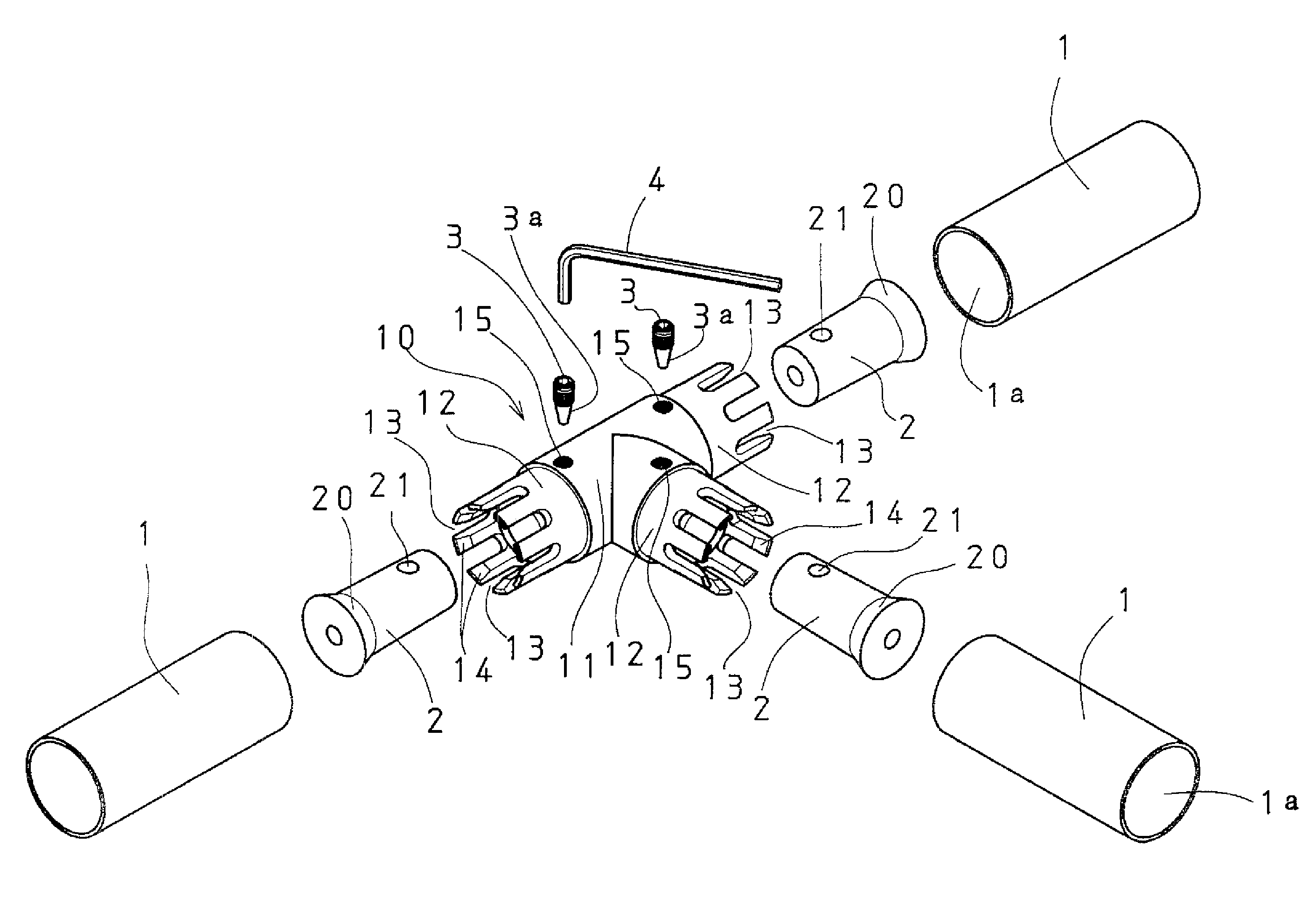
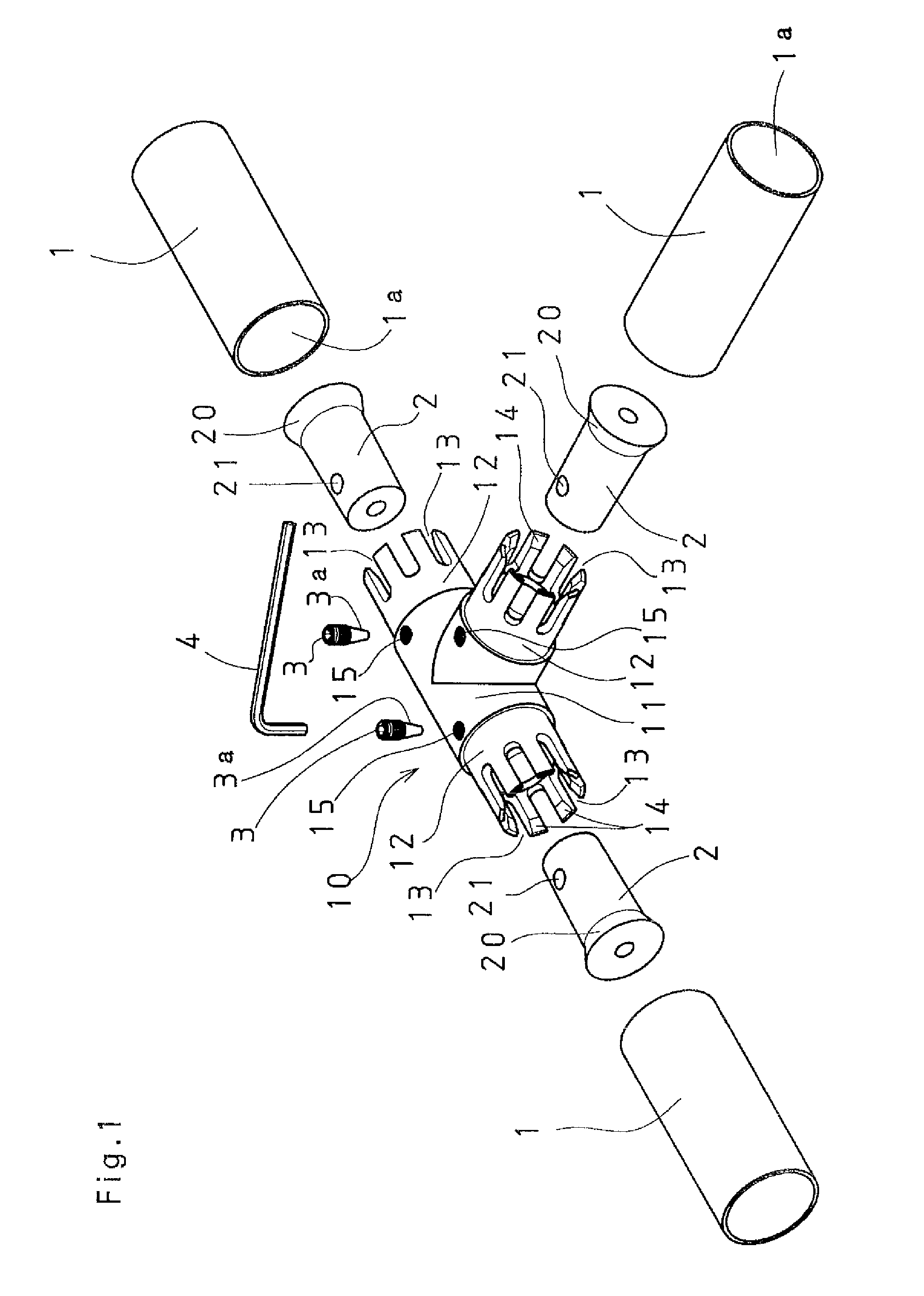
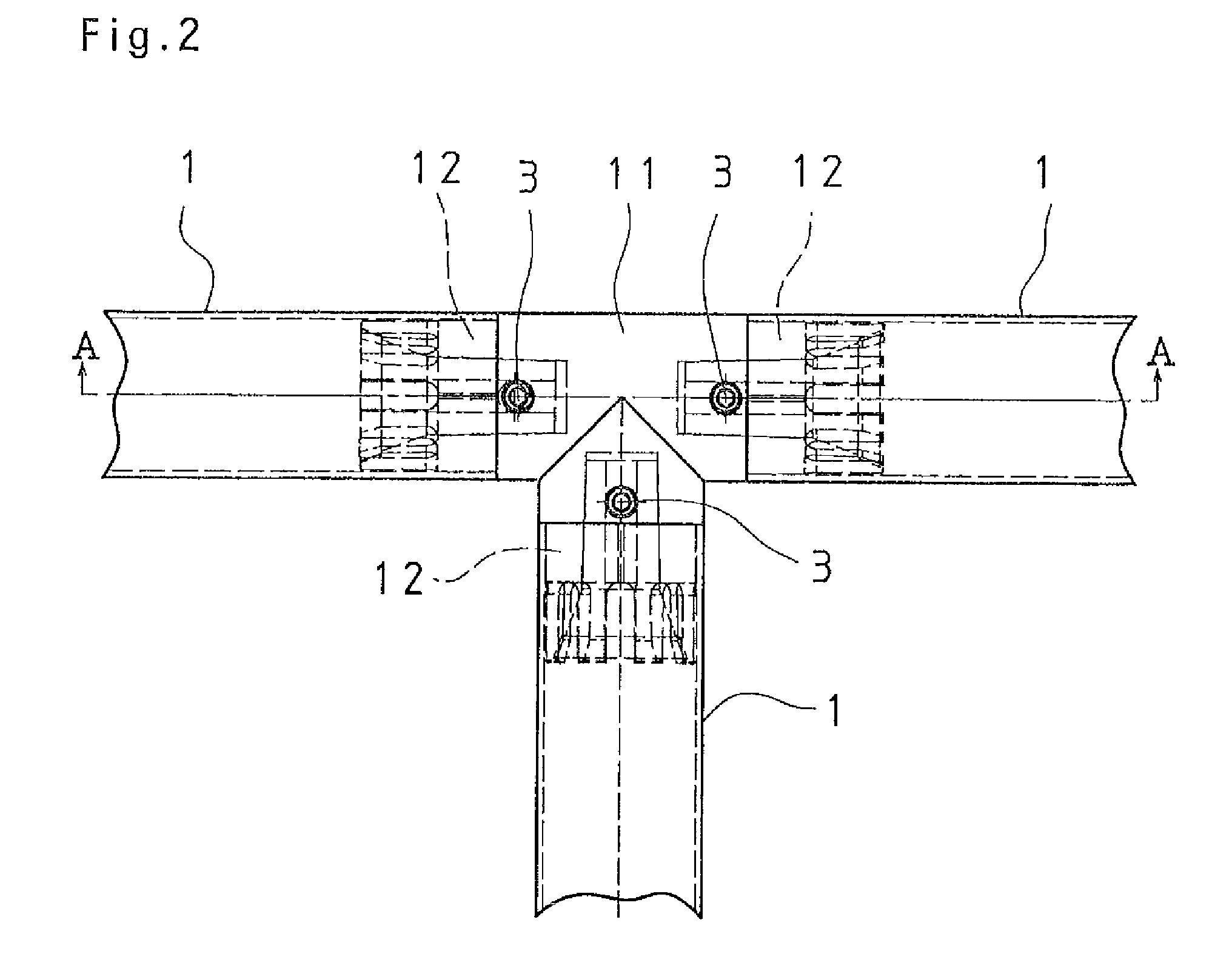
[0045]FIGS. 1 to 3 show an embodiment of the invention according to the first and second aspects. In a pipe joint 10 of the embodiment, three connecting inset portions 12, according to the embodiment shown in FIG. 1, which extend from a joint body 11 and are inserted in internal bores 1a of respective pipes to be connected 1, are each formed to have a hollow structure. A plurality of long slit-like splits 13 are formed in each of the connecting inset portions 12 at substantially regular intervals as viewed in a circumferential direction so as to axially extend from an end of the corresponding connecting inset portion 12 almost over an entire length of the connecting inset portion 12. This provides the connecting inset portion 12 with radial flexibility. The flexibility of the connecting inset portion 12 makes it easy to fit the connecting inset portion 12 into an internal bore 1a of a co...

embodiment 2

[0063]FIG. 7 shows an embodiment of the invention according to the third and fourth aspects.

[0064]A joint of Embodiment 2 (FIG. 7) has a basic structure identical in many points to Embodiment 1. To be concrete, a connecting inset portion 12 extending from a joint body 11 and inserted in an internal bore of a pipe to be connected 1 is formed to have a hollow structure. The connecting inset portion 12 has a plurality of long slit-like splits circumferentially arranged at substantially regular intervals so as to axially extend from an end of the connecting inset portion 12. In a hollow interior of the connecting inset portion 12, there is formed a tapered portion 14 having an internal diameter decreasing from the end thereof toward the joint body 11. The joint includes a tapered sleeve 2 to be inserted in the hollow interior of the connecting inset portion 12 of the joint body 11 and a stop bolt 3 having a conical portion 3a in an end portion thereof.

[0065]In Embodiment 2, as in Embodi...

embodiment 3

[0073]FIG. 8 shows an embodiment of the invention according to the fifth and sixth aspects.

[0074]A joint of Embodiment 3 has a basic structure identical in many points to Embodiments 1 and 2. More specifically, a connecting inset portion 12 extending from a joint body 11 and inserted in an internal bore of a pipe to be connected 1 is formed to have a hollow structure. The connecting inset portion 12 also has a plurality of long slit-like splits that are circumferentially arranged to axially extend from an end of the connecting inset portion 12. The connecting inset portion 12 is provided in a hollow interior thereof with a tapered portion 14 having an internal diameter decreasing from the end thereof toward the joint body. The joint includes a tapered sleeve 2 to be inserted in the hollow interior of the connecting inset portion 12 of the joint body 11 and a stop bolt 3 having a conical portion 3a in an end portion thereof.

[0075]In a rear part of the tapered sleeve 2 to be inserted ...


PUM


Abstract

The present invention provides a internal pipe joints suitable for connection when pipes used under light-load conditions, or to be more concrete, plastic coated steel pipes having an external diameter ranging from about 28 mm to about 45 mm, which are produced by coating the outer surfaces of thin steel pipes with synthetic resin in a thin layer, are assembled into a planar or three-dimensional pipe structure, and more specifically, relates to pipe joints that have high strength in pipe connection and is excellent in design for having a simple appearance design in the position connecting the pipes.
The present invention comprises a joint body in which one or more connecting inset portions extending from the joint body and each inserted in an internal bore of a corresponding pipe to be connected are each formed to have a hollow structure, a plurality of long slit-like splits are formed in each of the connecting inset portions in a circumferential direction to axially extend from an end of the corresponding connecting inset portion, and the connecting inset portion is further provided in a hollow interior thereof with a tapered portion having an internal diameter decreasing from the end thereof toward the joint body; a tapered sleeve to be inserted in the hollow interior of the connecting inset portion; and a stop bolt having a conical portion in an end portion thereof.

Description

BACKGROUND OF THE INVENTION[0001]1. Field of the Invention[0002]The present invention relates mainly to the technical field of internal pipe joints suitable for connection (or linking) when pipes used under light-load conditions, or to be more concrete, plastic coated steel pipes having an external diameter ranging from about 28 mm to about 45 mm, which are produced by coating the outer surfaces of thin steel pipes with synthetic resin in a thin layer, are assembled into a planar or three-dimensional pipe structure, and more specifically, relates to pipe joints that have high strength in pipe connection and is excellent in design for having a simple appearance design in the position connecting the pipes.[0003]2. Description of the Related Art[0004]As a joint for connecting pipes which assembles the pipes used under light-load conditions into a planar or three-dimensional pipe structure, an external joint in which a pipe is fitted to the socket of the joint has been conventionally kn...

Claims


Application Information

Patent Timeline
IPC IPC(8): F16F1/38
CPCE04B1/585Y10T403/405F16B7/0453F16B7/042
Inventor MINOWA, ISAMUYAZAKI, ATSUHIKO
Owner YAZAKI IND CHEM CO LTD
Learn More