
Arteriovenous fistula

a technology of arteriovenous fistula and shunt, which is applied in the field of shunt, can solve the problems of synthetic shunt wall sealing, percutaneous nature of synthetic shunt, and risk of infection, and achieve the effect of improving the sealing of the wall

Inactive Publication Date: 2010-01-14
CR BARD INC
View PDF14 Cites 19 Cited by
  • Summary
  • Abstract
  • Description
  • Claims
  • Application Information

AI Technical Summary

Benefits of technology

[0011]In a first aspect, this invention provides a covered radially expansible stent, capable of being advanced along a bodily lumen, and capable of performing as an arteriovenous shunt. The shunt is one that is “stickable”, that is to say, it can endure repeated puncturing with a dialysis needle. The shunt is located subcutaneously, so that the only element that is percutaneous during dialysis is the dialysis needle. One way to enhance sealing of the wall of the shunt, when dialysis is completed and the needle is withdrawn, is to provide a special gel between the puncture site and the skin overlaying it. The special gel may be the one marketed under the trademark EGRESS. The shunt resembles a stent graft, known per se, in which a metal stent matrix of struts is covered by a thin membrane of expanded polytetrafluoroethylene (ePTFE).
[0021]To enable the advance of the catheter containing the shunt, from the artery across to the vein, it is preferred to use a tunneling device to tunnel between a percutaneous slit adjacent the artery where its wall is to be broached, and a second percutaneous slit adjacent the vein where the lumen wall of the vein is to be broached radially inwardly. With access provided with the two percutaneous slits, a tunneling needle can be advanced form one slit to the other and it may be convenient to use the tunneling needle not only to establish a channel through the tissue to receive the shunt delivery catheter, but also to install temporarily in that channel a sheath through which the delivery catheter can advance, said sheath being withdrawn afterwards, through one of the percutaneous slits.
[0023]The puncture site in the shunt does not have the capacity for natural healing but does have a capability for a high degree of sealing, through its natural resilience. The blood tightness of the punctured shunt can be enhanced by the provision of a pillow or pad of gel located between the puncture site of the shunt and the overlying cutaneous layers of natural tissue.
[0024]In this way, the present invention offers possibilities to enhance the quality of life of dialysis patients, and reduce the likelihood of percutaneous infection. Furthermore, by sparing arterial and venous wall tissue the trauma of repeated needle sticks, the likelihood of local stenosis of the arterial or venous lumens can be reduced.

Problems solved by technology

However, there remains the problem of reliable sealing of the synthetic shunt wall, and the risks of infection arising from the percutaneous nature of the synthetic shunt.

Method used


Image

  • Arteriovenous fistula
  • Arteriovenous fistula
  • Arteriovenous fistula

Examples


Embodiment Construction

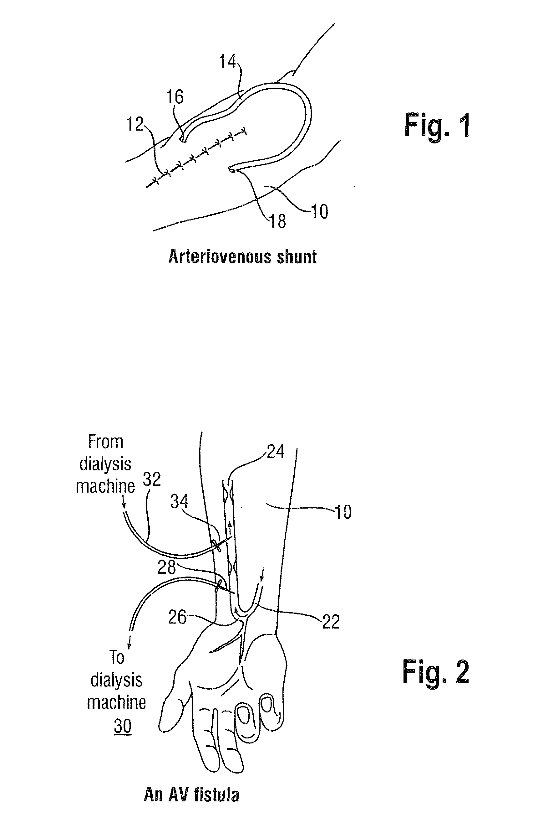
[0036]Looking first at FIG. 1, there is shown a human forearm 10 with a stitched together long percutaneous slit 12 and an arteriovenous shunt 14 with one end 16 extending through a percutaneous puncture into an arterial lumen of the forearm, and an opposite end 18 extending through a percutaneous puncture spaced from puncture 16, and into a venous lumen of the forearm. The shunt intermediate length portion is external of the body and therefore available for access by dialysis needles. However, the puncture sites 16 and 18 render the arrangement less than ideal from an infection perspective.

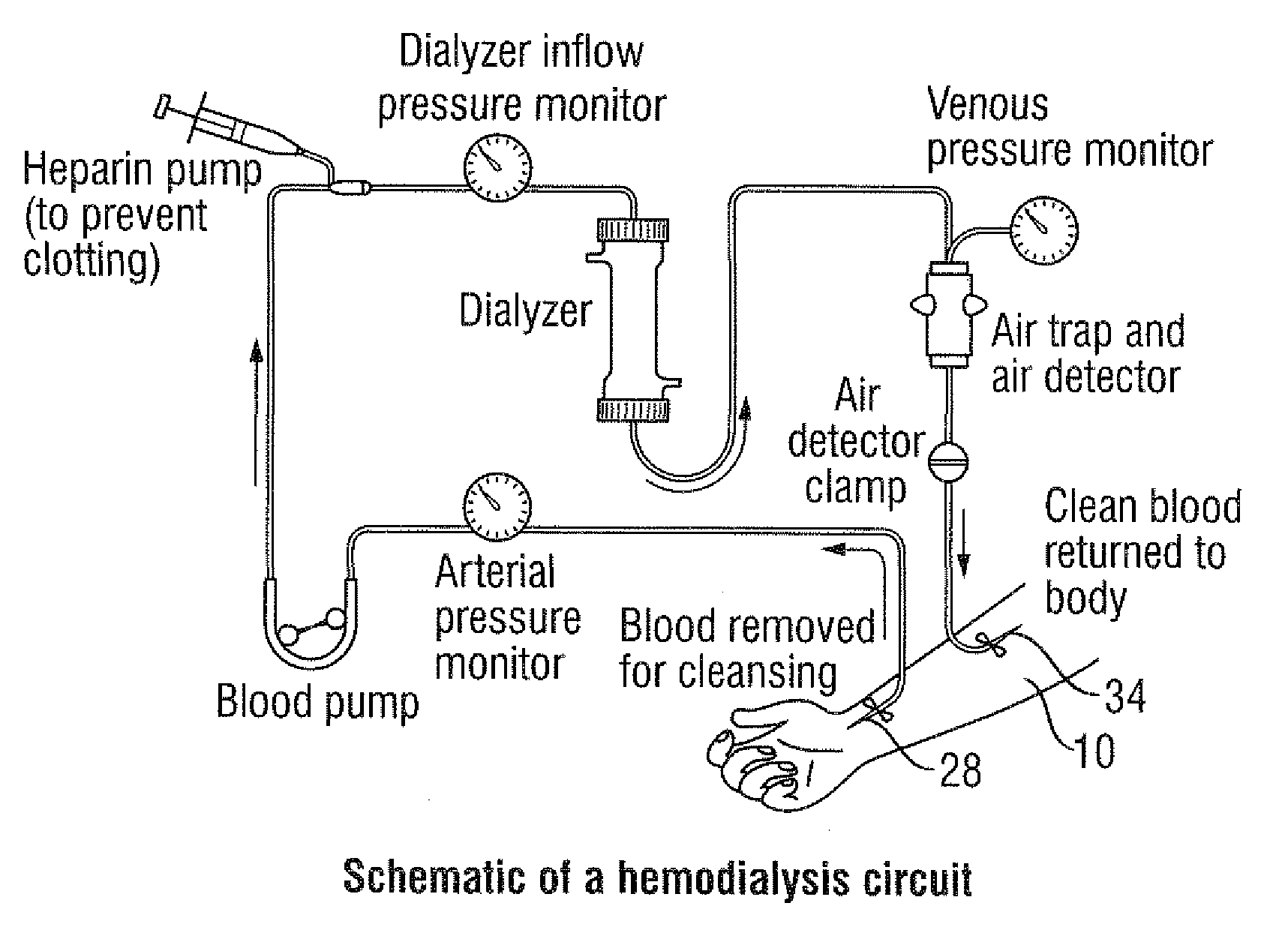
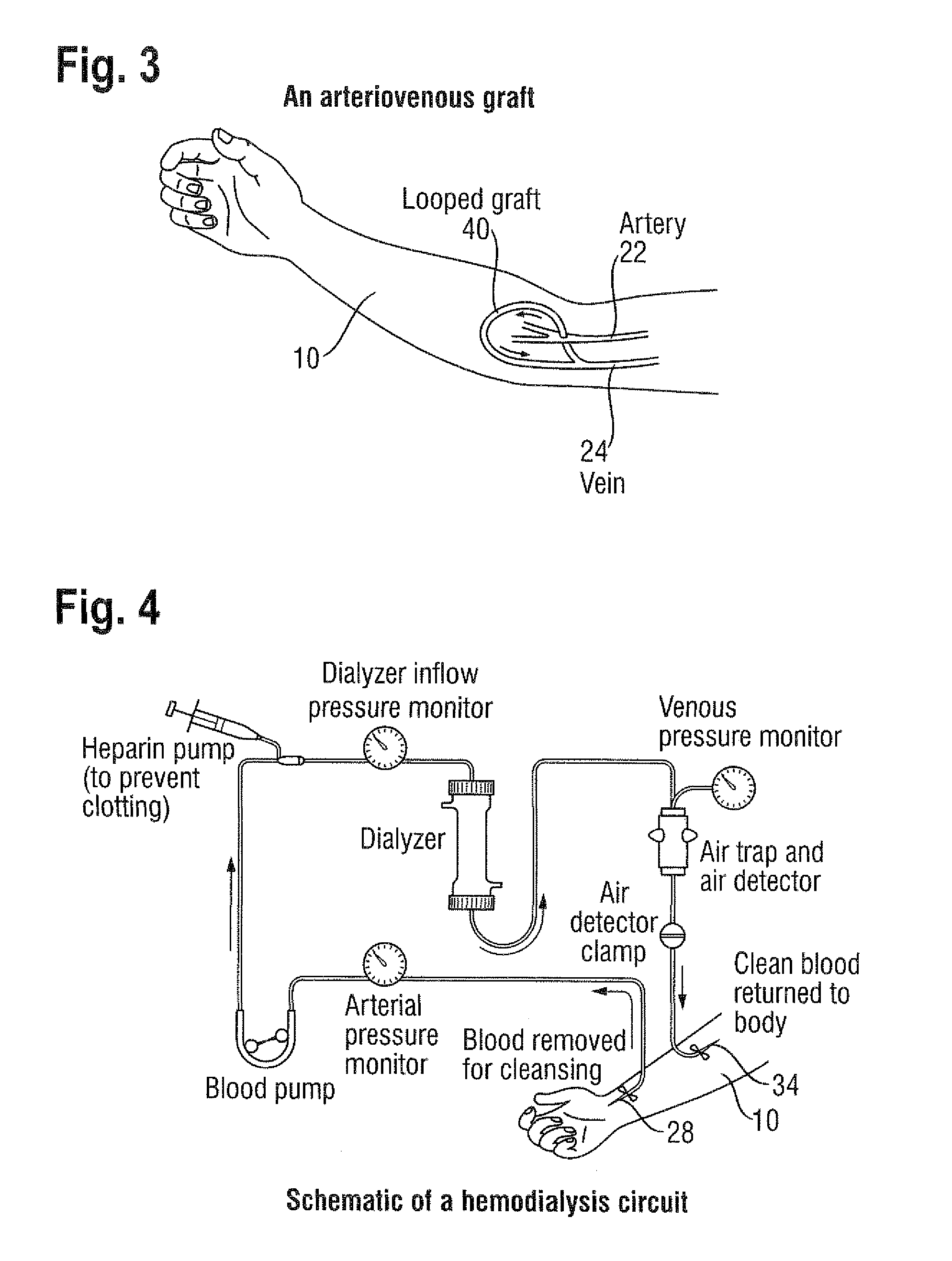
[0037]Turning to FIG. 2, there is shown again the human forearm 10 and, diagrammatically, beneath the skin, an arterial lumen 22, a venous lumen 24 and, between them, an arteriovenous fistula 26. A first dialysis needle 28 taps blood for a dialysis machine 30 and a return flow channel 32 from the machine delivers blood back to the patient via a second dialysis needle 34.

[0038]Looking at FIG. 3, w...


PUM


Abstract

A covered radially-expansible stent (50), capable of being advanced along a bodily lumen, and capable of performing as an arteriovenous shunt, and with a covering that stops short of one end of the stent at a line that slants to the longitudinal axis of the stent at an angle intermediate between 0° and 90°.

Description

TECHNICAL FIELD[0001]This invention relates to a shunt for providing an arteriovenous fistula, a system for placing the shunt and a method for placing the shunt.[0002]Individuals suffering from renal failure undergo haemodialysis, in which a dialysis machine performs the function of the failed kidneys. Haemodialysis has to be repeated periodically and frequently and this requires repeated puncturing of the arteriovenous system using relatively large diameter dialysis needles. Frequent puncturing of native vessels with large bore needles can cause trauma and eventually a loss of patency of those vessels.BACKGROUND ART[0003]It has previously been proposed to provider externally of the body, an arteriovenous shunt that can be accessed with a dialysis needle, thereby to relieve the individual of the adverse effects of repeated puncturing of native vessels. However, there remains the problem of reliable sealing of the synthetic shunt wall, and the risks of infection arising from the perc...

Claims


Application Information

Patent Timeline
Patent Type & Authority Applications(United States)
IPC IPC(8): A61F2/06A61F2/91
CPCA61M1/3655A61F2/91
Inventor DORN, JURGEN
Owner CR BARD INC
Learn More