Vibration suppressing method and device

a technology of vibration suppression and vibration, applied in the direction of fluid pressure measurement by mechanical elements, solid vibration measurement, machine part testing, etc., can solve the problems of high cost, time and effort, and high technique, so as to effectively suppress the wear of tools, improve the quality of workpiece surfaces, and suppress the effect of continuously generated vibration

Inactive Publication Date: 2010-01-14
OKUMA CORP
View PDF15 Cites 37 Cited by
  • Summary
  • Abstract
  • Description
  • Claims
  • Application Information

AI Technical Summary

Benefits of technology

[0020]According to the first to the fifth aspects of the present invention, when the “chatter vibration” is generated again at a rotary shaft during rotation at an expected stable rotation speed, a rotation speed of the rotary shaft is changed based on the expected stable rotation speed so as to correspond to the chatter vibration. Thus, the “chatter vibration” that is continuously generated can be suppressed more effectively than a conventional method, which improves a quality of a workpiece surface and effectively suppresses a tool wear.
[0021]Further, the stable rotation speed is determined by acquiring an amount of change of a k′ number and an amount of change of a chatter frequency when the rotation speed is changed, comparing these amounts of change with a phase threshold value, and the like. Consequently, a more accurate stable rotation speed can be acquired and the “chatter vibration” can be suppressed effectively.
[0022]According to the sixth to the eighth aspects of the present invention, when a “chatter vibration” is generated, calculating the phase ε1 at the rotation speed and comparing the calculated phase ε1 with the phase ε0 at the rotation speed when the vibrational acceleration previously exceeds a predetermined threshold value, the rotation speed of the rotary shaft is changed according to the result of comparison. Therefore, a response according to a situation can be made, and an influence of a “regenerative chatter vibration” can be suppressed.
[0023]Particularly, comparing the phase ε1 at the current rotation speed with the phase ε0 at the previous rotation speed, then, if the phase ε1 is equal to or larger than the phase ε0, the rotation speed is changed to the previous rotation speed (that is, the rotation speed at the time of calculating the phase ε0). Thus, machining can be performed at the rotation speed having a minimum phase value. Therefore, generation of the “regenerative chatter vibration” can be suppressed more effectively, which improves a quality of a workpiece surface and suppresses a tool wear.

Problems solved by technology

However, as for the vibration suppressing method disclosed in Japanese Unexamined Patent Publication No. 2003-340627, an impulse device with high cost is necessary.
Further, a high technique is required for an excitation using this device, and it takes time and effort.
Furthermore, since a characteristic frequency acquired before machining does not necessarily coincide with a characteristic frequency generated during machining, there is a problem that an accurate stable rotation speed is hardly acquired.
However, as for this vibration suppressing device, there might be a calculation discrepancy between the characteristic frequency calculated during machining by the calculating unit and the actual characteristic frequency due to an error of the calculation formula, and thus a situation that the chatter vibration is continued to be generated even when the rotary shaft is made to have the stable rotation speed might be considered.

Method used


Image

  • Vibration suppressing method and device
  • Vibration suppressing method and device
  • Vibration suppressing method and device

Examples


first embodiment

A First Embodiment

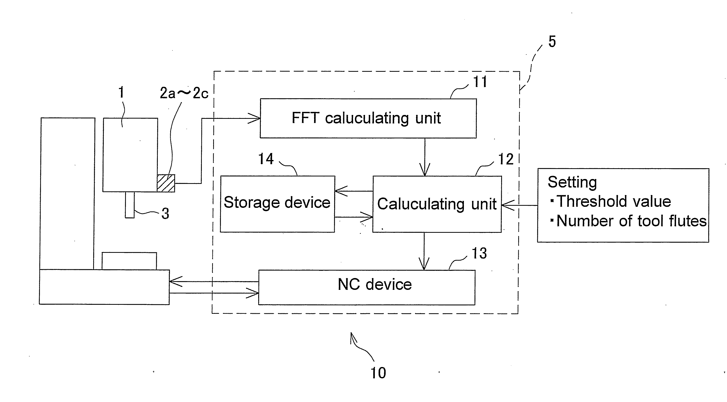
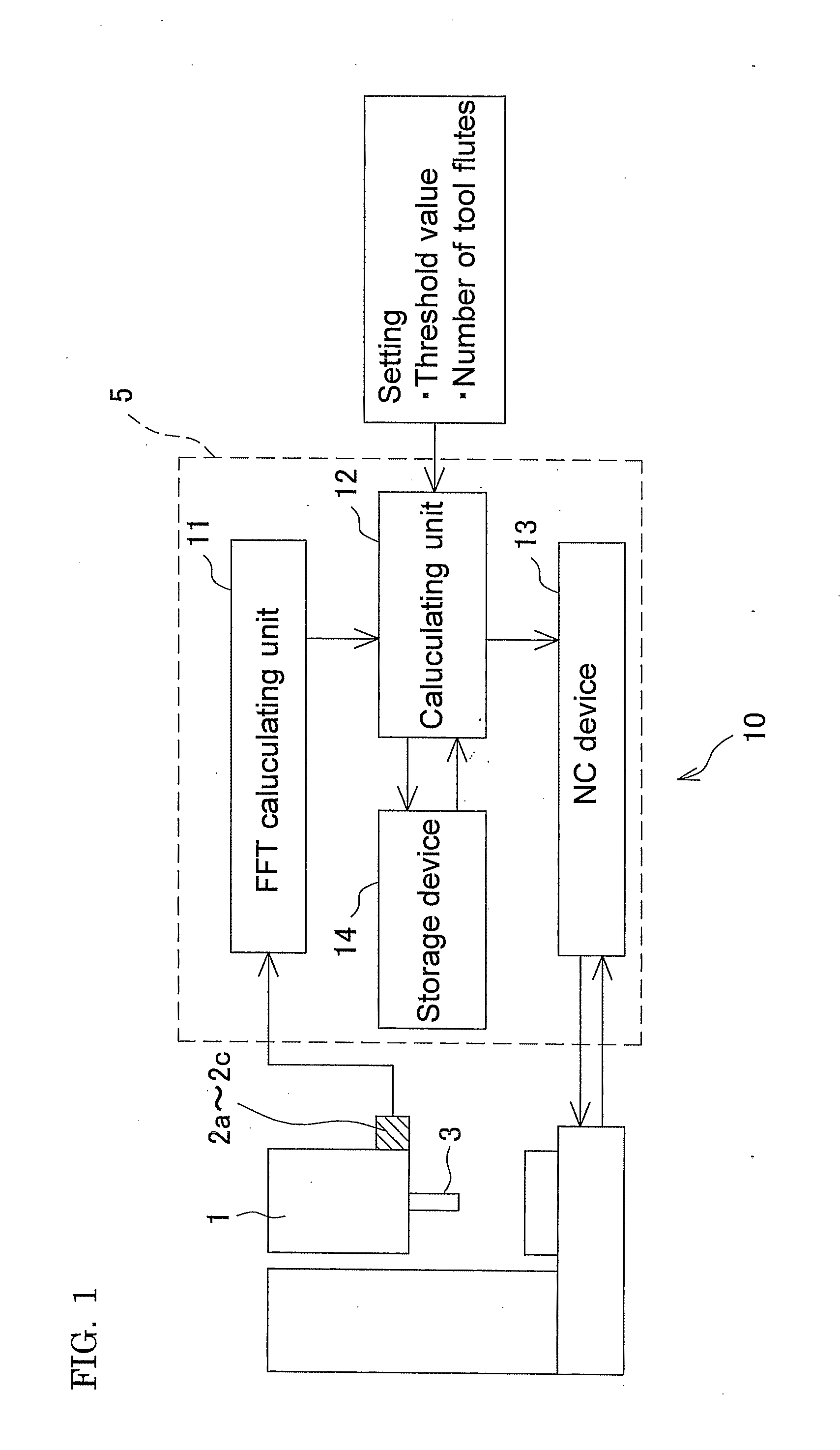
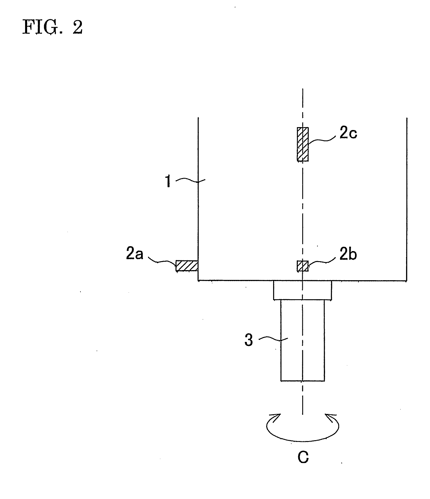
[0036]The vibration suppressing device 10 intends to suppress “chatter vibration” that is generated at a rotary shaft 3 rotatably provided around a C axis of the rotary shaft housing 1. The vibration suppressing device 10 includes vibration sensors (a detection unit) 2a to 2c for detecting a time-domain vibrational acceleration (it means a vibrational acceleration on a time axis) to be generated at the rotary shaft 3 during rotation, and a control device 5 for controlling a rotation speed of the rotary shaft 3 based on values detected by the vibration sensors 2a to 2c.

[0037]As illustrated in FIGS. 2 and 3, the vibration sensors 2a to 2c are mounted on the rotary shaft housing 1 in a state capable of detecting the time-domain vibrational accelerations in directions of an X axis, a Y axis, and a Z axis which are perpendicular to one another to detect the time-domain vibrational accelerations in the directions which are orthogonal to each other.

[0038]Further, the con...

second embodiment

A Second Embodiment

[0051]The storage unit 14 of the control device 5 of the vibration suppressing device 10 according to a second embodiment of the present invention stores an initial value (ε0=1) of the phase ε0. Other configurations of the vibration suppressing device 10 according to the second embodiment of the present invention are the same as those of the first embodiment of the present invention.

[0052]Here, a vibration suppressing method of “chatter vibration” by the vibration suppressing device 10 will be described referring to a flowchart in FIG. 11.

[0053]At the beginning of machining, the control device 5 controls the rotating operation of the rotary shaft 3 based on the flowchart in FIG. 11.

[0054]First, the FFT calculating unit 11 performs Fourier-analysis of the time-domain vibrational accelerations which are constantly detected during the rotation of the rotary shaft 3 by the vibration sensors 2a to 2c (S1), and constantly calculates a maximum acceleration (a frequency-d...


PUM


Abstract

A stable rotation speed is acquired by finely changing a rotation speed of a rotary shaft 3 based on an expected stable rotation speed, and calculating an amount of change of a k′ number, and the like. Therefore, a more accurate rotation speed can be acquired, and “chatter vibration” generated during machining can be suppressed more effectively than a conventional method. As a result, a quality of a workpiece surface can be improved, and a tool wear and the like can be suppressed.

Description

BACKGROUND OF THE INVENTION[0001]This application claims the benefit of Japanese Patent Application Numbers 2008-178300 filed on Jul. 8, 2008 and 2008-274611 filed on Oct. 24, 2008, the entirety of which is incorporated by reference.[0002]1. Field of the Invention[0003]The present invention relates to a method for suppressing vibration generated during machining in a machine tool for performing machining while rotating a tool or a work, and a vibration suppressing device capable of executing this method.[0004]2. Description of the Related Art[0005]As for a vibration suppressing method of a machine tool, for example, a method disclosed in Japanese Unexamined Patent Publication No. 2003-340627 is conventionally known. According to this vibration suppressing method, in order to suppress regenerative type chatter vibration as self-excited vibration causing a low finishing workpiece surface roughness, a characteristic frequency of a system generating chatter vibration is obtained, e.g., ...

Claims


Application Information

Patent Timeline
Patent Type & Authority Applications(United States)
IPC IPC(8): G06F19/00
CPCB23Q17/0976B23Q11/0039
Inventor INAGAKI, HIROSHI
Owner OKUMA CORP
Why Eureka
Try Eureka