Ethane Recovery Methods And Configurations

Active Publication Date: 2010-01-21
FLUOR TECH CORP
View PDF18 Cites 42 Cited by
  • Summary
  • Abstract
  • Description
  • Claims
  • Application Information

AI Technical Summary

Benefits of technology

[0009]The present invention is directed to configurations and methods in which a relatively high pressure of a CO2-containing feed gas with relatively low C3+ content is employed to provide cooling and energy for recompression while at the same time maximizing ethane recovery. Most prefer

Problems solved by technology

Most of the conventional processes require propane refrigeration for feed gas chilling and/or reflux condensing in the demethanizer and/or demethanizer, and where feed gas pressure is low or contains significant quantity of propane and heavier components, demand for propane refrigeration is often substantial, adding significant expense to the NGL recovery process.
While such configurations are often economical and effective for feed gas with relatively high C3+ (e.g., greater than 3 mol %) content, and feed gas pressure of about 1000 psig or less, they are generally not energy efficient for low C3+ content (e.g., equal or less than 3 mol %, and more typically less than 1 mol %), and particularly where the feed gas has a relatively high pressure (e.g. 1400 psig and higher).
Unfortunately, in many known expander processes, residue gas from the fractionation column still contains significant amounts of ethane and propane that could be recovered if chilled to an even lower temperature, or subjected to another rectification stage.
However, the increase in demethanizer pressure is typically limited to between 450 psig to 550 psig as higher column pressure will decrease the relative volatilities between the methane and ethane components, making fractionation difficult, if not even impossible.
Consequently, excess cooling is generated by the turbo-expansion from most high pressure feed gases, which heretofore known processes cannot fully utilize.
Unfortunat

Method used


Image

  • Ethane Recovery Methods And Configurations
  • Ethane Recovery Methods And Configurations
  • Ethane Recovery Methods And Configurations

Examples


Embodiment Construction

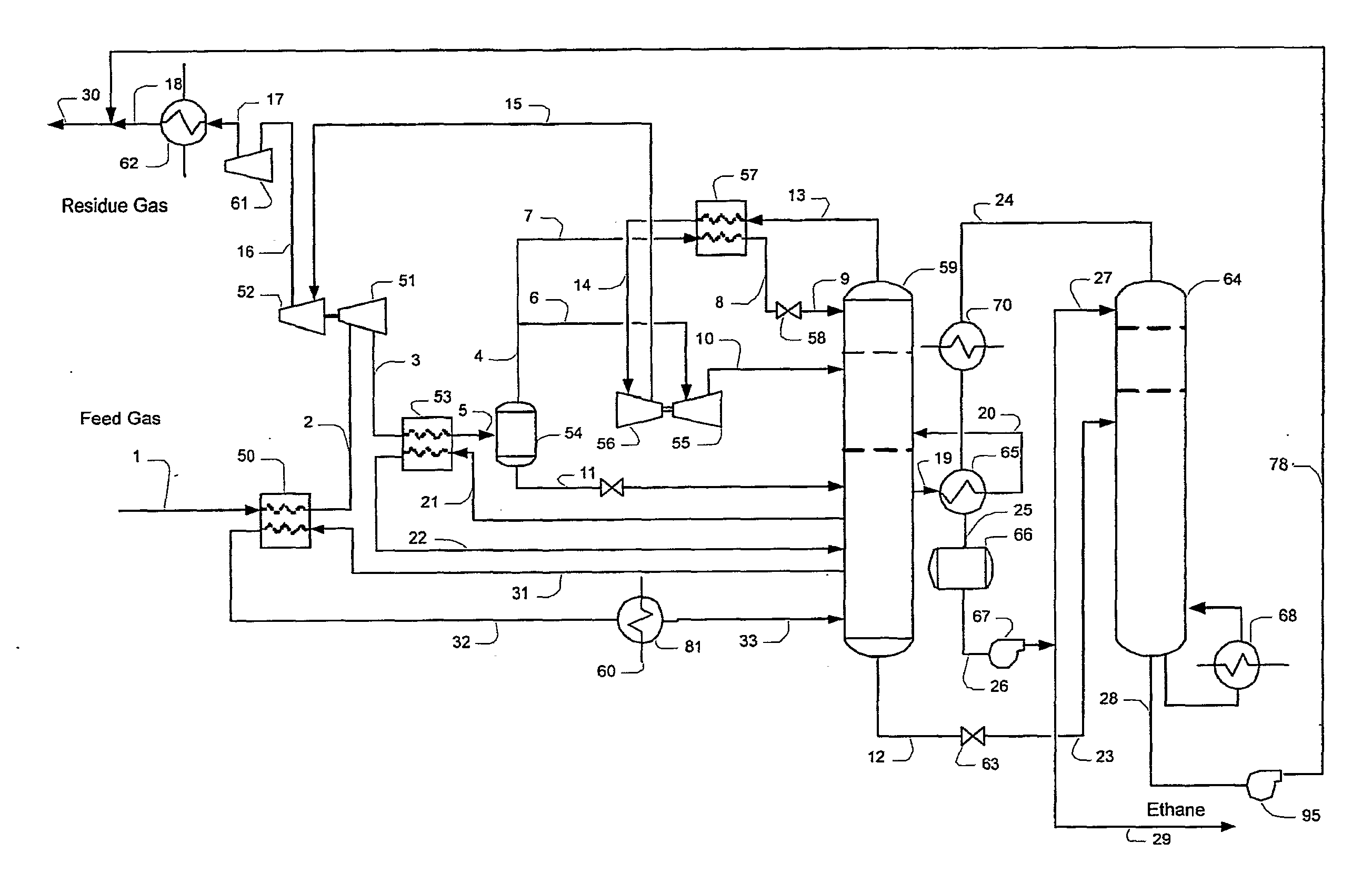
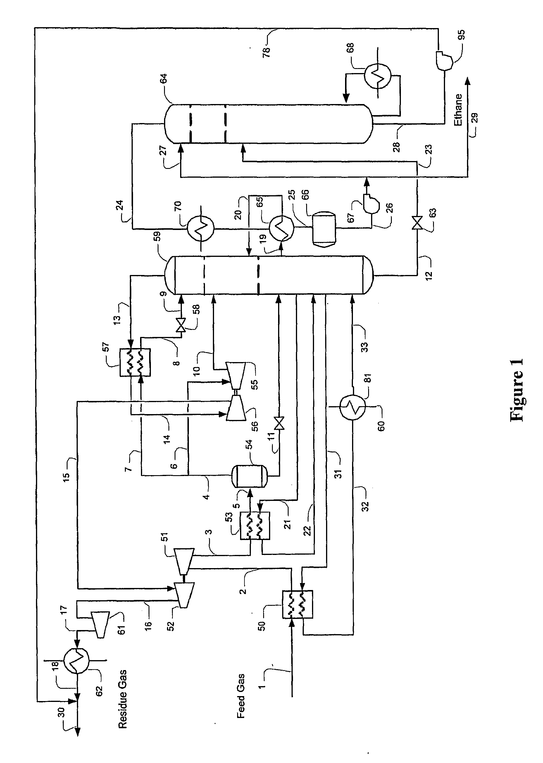
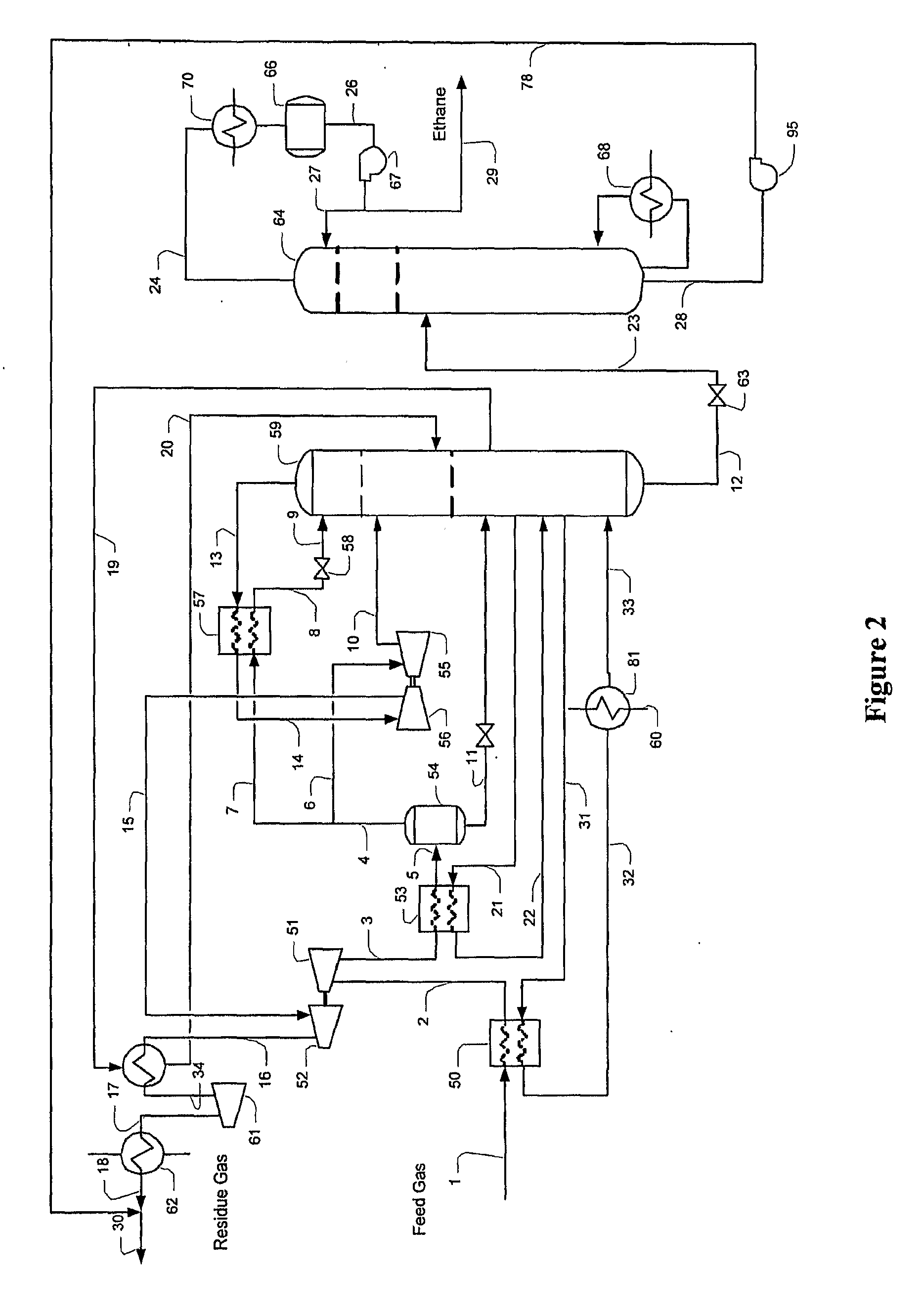
[0017]The inventor has discovered that various high pressure hydrocarbon feed gases (e.g. at least 1400 psig, and more preferably at least 1600 psig, and even higher) can be processed in configurations and methods that include two stages of turbo-expansion that will significantly contribute to the cooling requirements of a downstream demethanizer and deethanizer. The feed gas in preferred aspects comprises CO2 in an amount of at least 0.5 mol %, and more typically at least 1-2 mol %, and has a relatively low C3+ (i.e., C3 and higher) content that is typically equal or less than 3 mol %.

[0018]In most of contemplated configurations and methods, ethane recovery of at least 70% to 95% is achieved while refrigeration and energy requirements are dramatically reduced. Moreover, in especially preferred configurations and methods, the demethanizer reboiler duty is provided by the feed gas heat content, and expansion of the feed gas provides refrigeration content in the reflux and demethanize...


PUM


Abstract

Contemplated methods and configurations use a cooled ethane and CO2-containing feed gas that is expanded in a first turbo-expander and subsequently heat-exchanged to allow for relatively high expander inlet temperatures to a second turbo expander. Consequently, the relatively warm demethanizer feed from the second expander effectively removes CO2 from the ethane product and prevents carbon dioxide freezing in the demethanizer, while another portion of the heat-exchanged and expanded feed gas is further chilled and reduced in pressure to form a lean reflux for high ethane recovery.

Description

[0001]This application claims priority to our copending U.S. provisional patent application with the Ser. No. 60 / 817169, which was filed Jun. 27, 2006.FIELD OF THE INVENTION[0002]The field of the invention is gas processing, and especially as it relates to natural gas processing for ethane recovery.BACKGROUND OF THE INVENTION[0003]Various expansion processes are known for hydrocarbon liquids recovery, especially in the recovery of ethane and propane from high pressure feed gas. Most of the conventional processes require propane refrigeration for feed gas chilling and / or reflux condensing in the demethanizer and / or demethanizer, and where feed gas pressure is low or contains significant quantity of propane and heavier components, demand for propane refrigeration is often substantial, adding significant expense to the NGL recovery process.[0004]To reduce external propane refrigeration requirements, the feed gas can be cooled and partially condensed by heat exchange with the demethaniz...

Claims


Application Information

Patent Timeline
IPC IPC(8): F25J3/00
CPCF25J3/0209F25J2270/60F25J3/0238F25J3/0242F25J2200/02F25J2200/04F25J2200/50F25J2200/70F25J2200/72F25J2205/04F25J2215/02F25J2215/62F25J2220/66F25J2240/02F25J2245/02F25J2270/12F25J3/0233F25J2215/60
Inventor MAK, JOHN
Owner FLUOR TECH CORP
Why Eureka
Try Eureka