Wine pouring regulator and aerator therein

a technology of pouring regulator and aerator, which is applied in the directions of milk preservation, transportation and packaging, pliable tubular containers, etc., can solve the problems of affecting the flow of water, so as to reduce the amount of water in the glass, and reduce the effect of spurting

a technology of pouring regulator and aerator, which is applied in the directions of milk preservation, transportation and packaging, pliable tubular containers, etc., can solve the problems of affecting the flow of water, so as to reduce the amount of water in the glass, and reduce the effect of spurting

US20100011967A1Inactive Publication Date: 2010-01-21BARBERIO JANET +1

Image

  • Wine pouring regulator and aerator therein
  • Wine pouring regulator and aerator therein
  • Wine pouring regulator and aerator therein

Examples


Embodiment Construction

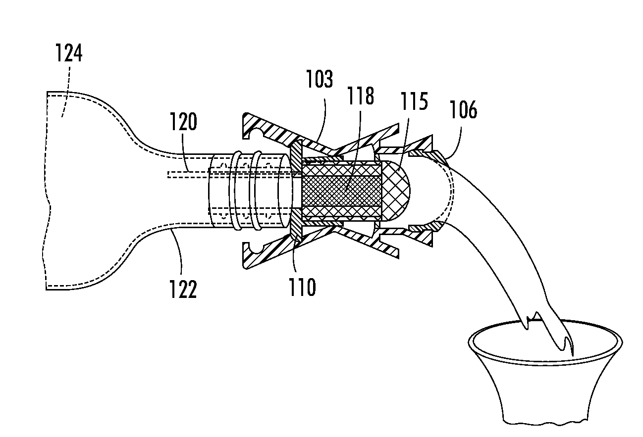
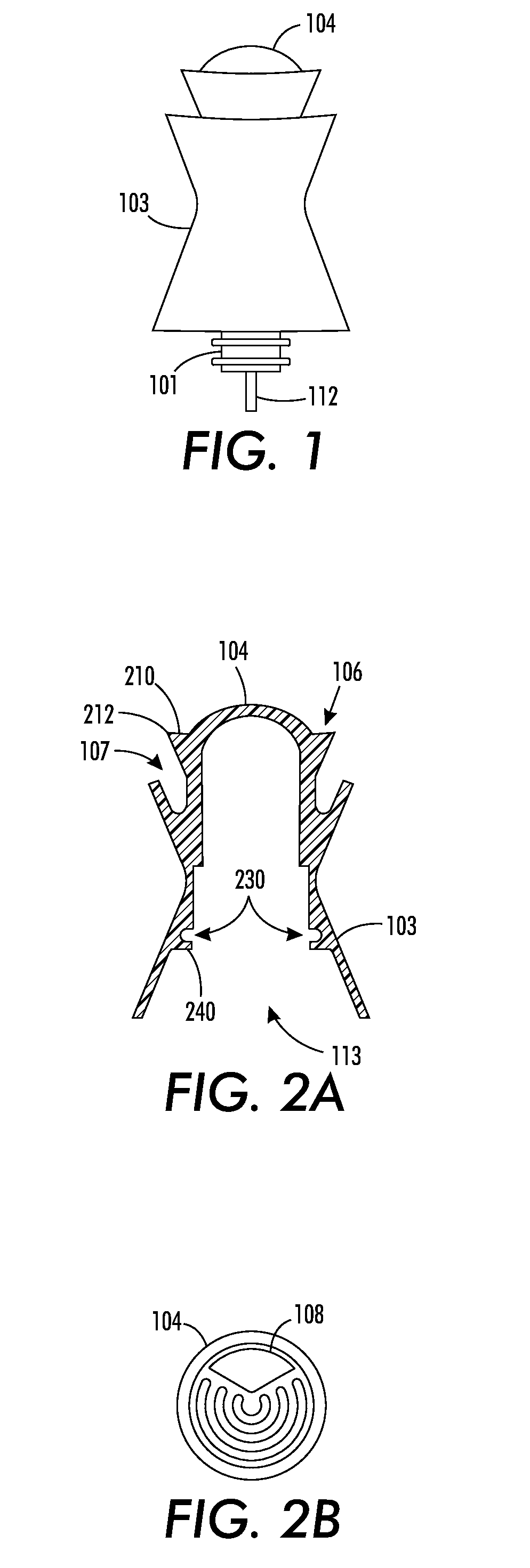
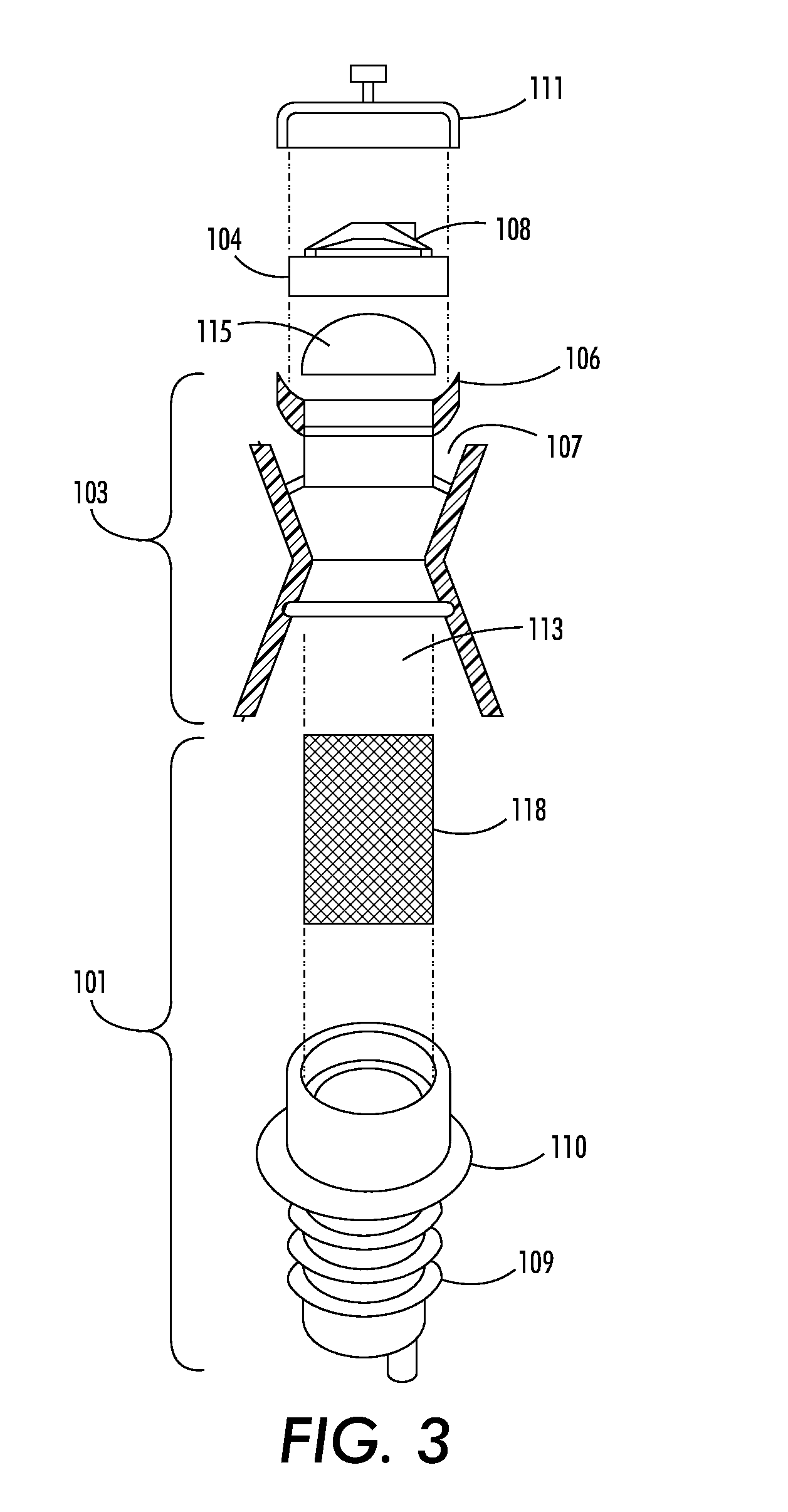
[0026]As depicted in FIG. 1 the wine pouring regulator and aerator of the disclosed embodiment includes a dome 104 that is indexed to, and fits securely within housing 103. Dome 104, as viewed in FIG. 2, includes openings 108 to pass the wine therethrough and also provides an indicia to identify the desired radial orientation of the bottle while pouring, thereby allowing for the proper positioning of housing 103 to ensure that the orientation of air vent 112 is aligned with openings 108. In an alternative embodiment cap 111 (FIG. 3) is constructed without openings, to provide a cover to seal the regulator and wine bottle, as well as to prevent any foreign material present in the atmosphere from finding their way into the bottle, most importantly insects.

[0027]Referring also to FIG. 3, cylindrical housing 103, includes pouring rim 106 and related trough 107, as well as openings 108. Housing 103 has a diameter varying between about 1.0 inches to about 2.0 inches, although it will be a...


PUM

PropertyMeasurementUnit
diameteraaaaaaaaaa
diameteraaaaaaaaaa
diameteraaaaaaaaaa

Abstract

A bottle top regulator / aerator for controlling the flow from a bottle having a narrow cylindrical opening through which wine or similar liquid may be poured. The dispensing apparatus includes, in combination, an air inductor, a regulating cartridge having a percolation labyrinth, and an anti-drip trough integrated within a housing. The application of this apparatus provides for both the rapid aeration of the wine, as well as a uniform flow rate absent the hazard of post-pouring droplets.

Description

[0001]This application claims priority from U.S. Provisional Patent Application 60 / 954,147, for a “WINE POURING REGULATOR AND AERATOR THEREIN,” filed Aug. 6, 2007 by J. Barberio et al., which is hereby incorporated by reference in its entirety.[0002]The disclosed apparatus relates to a device for controlling the flow of a liquid from a container, such as a bottle, having a narrow cylindrical opening through which wine or similar liquid may be poured, for example. The dispensing apparatus includes, a regulating cartridge, having a percolation labyrinth therein, and an anti-drip trough integrated with a pouring orifice. The use of the disclosed apparatus provides both aeration of the poured liquid, such as a wine, as well as a uniform flow rate, thereby reducing the hazard of dripping and splashing of wine while pouring.BACKGROUND AND SUMMARY[0003]Devices adapted for use in the aeration of wine have predominantly employed pneumatic pumps, which force air into the wine. For example U.S...

Claims


Application Information

Patent Timeline
21 Jan 2010
Publication
US20100011967A1
IPC
B01F3/04
CPC
B01F3/0446; B01F2215/0072; B01F5/0693; B01F5/0682; B01F23/232; B01F25/45; B01F25/4523; B01F2101/17
Inventors
BARBERIO, JANET; BRENNAN, PAUL J.