
Fuel Injectors with Intensified Fuel Storage and Methods of Operating an Engine Therewith

a fuel storage and fuel injection technology, applied in the direction of fuel injection with fuel accumulator, fuel injection apparatus, charge feed system, etc., can solve the problems of system serious drawbacks, engine hydraulic lock, unburned fuel levels in the exhaust,

Inactive Publication Date: 2010-01-21
STURMAN DIGITAL SYST
View PDF99 Cites 25 Cited by
  • Summary
  • Abstract
  • Description
  • Claims
  • Application Information

AI Technical Summary

Benefits of technology

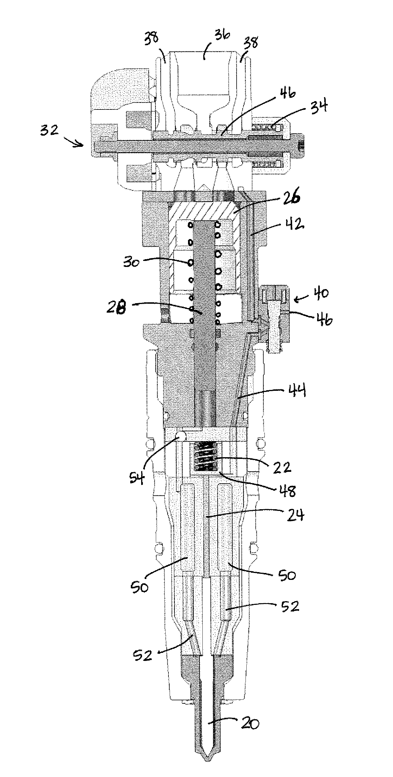
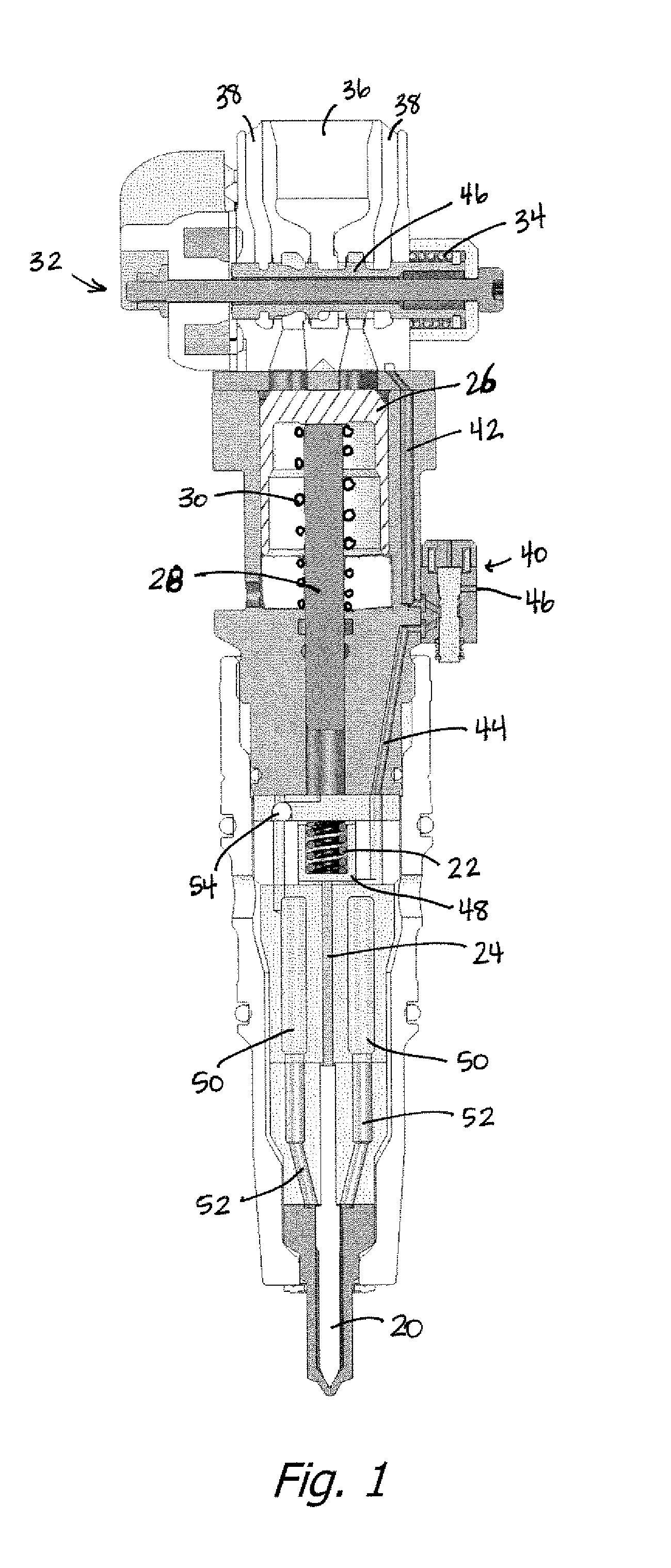
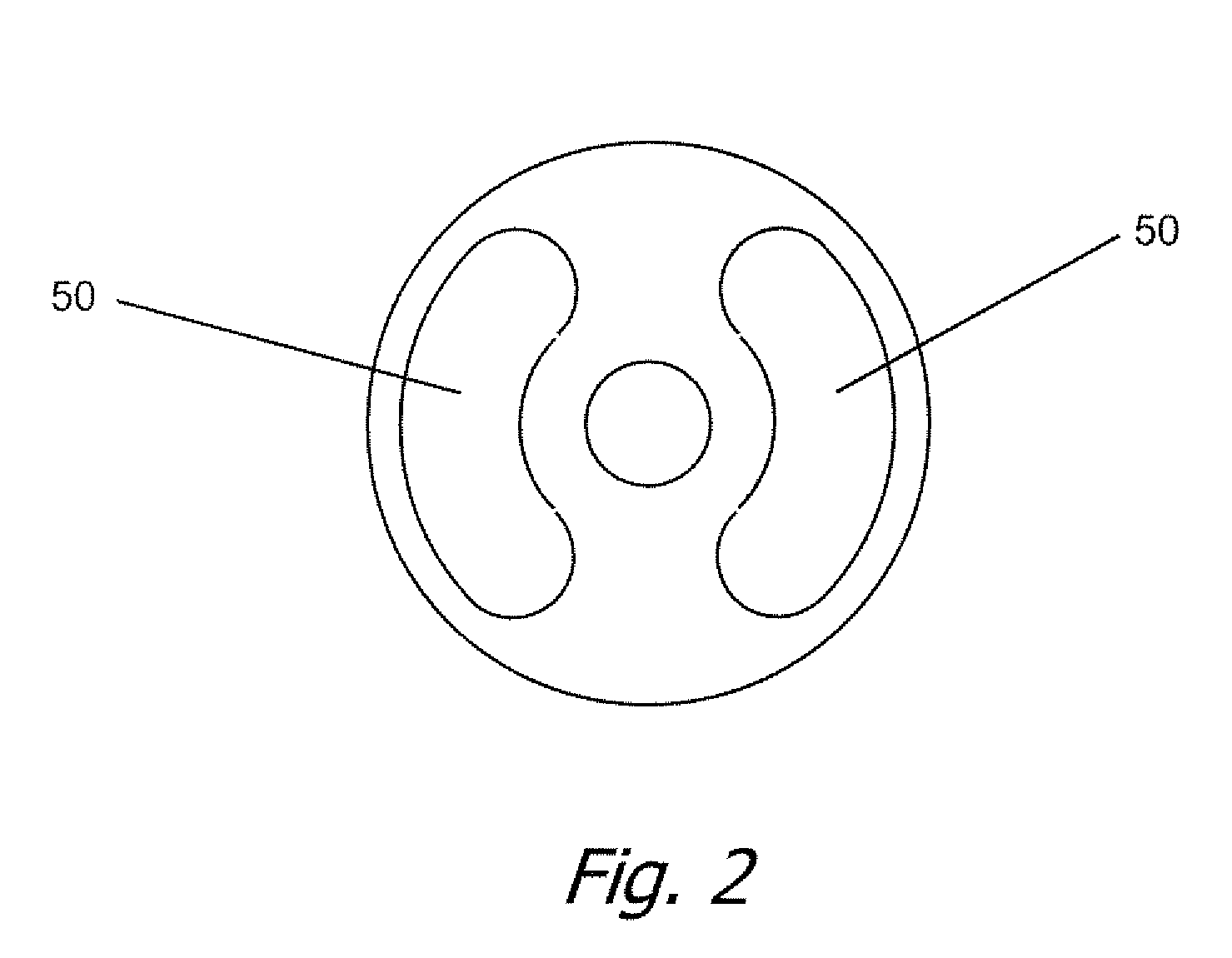
[0017]The present invention provides all the advantages and eliminates the disadvantages of a fuel rail at high injection pressures. In that regard, preferably the total storage volume, intensifier plus storage in porting and storage 50, is less than that that would cause a hydraulic lock in the engine cylinder is dumped into the cylinder on breakage of the injector tip. Also, the storage volume should not be so large as to jeopardize the structural integrity of the injector. Of course, while one exemplary form of direct needle control has been disclosed for purposes of setting the environment for the present invention, substantially any form of direct needle control may be used. Also while the check valve 54 is shown as a ball valve, other forms of check valves may also be used.

Problems solved by technology

In particular, if fuel injection is terminated merely by the reduction in injection pressure it is difficult to rapidly terminate injection because of the compressability of the fuel and actuation fluid in an intensifier type fuel injector, resulting in a trail off in atomization resulting in unacceptable levels of unburned fuel in the exhaust.
However such systems have serious drawbacks.
Aside from the safety issues of having a rail at injection pressures and the associated plumbing problems, there is a serious risk to the engine, in that if an injection tip breaks off, a direct and continuous flow path from the high pressure rail to the combustion chamber is provided, which could result in a hydraulic lock of the engine with catastrophic results.

Method used


Image

  • Fuel Injectors with Intensified Fuel Storage and Methods of Operating an Engine Therewith
  • Fuel Injectors with Intensified Fuel Storage and Methods of Operating an Engine Therewith
  • Fuel Injectors with Intensified Fuel Storage and Methods of Operating an Engine Therewith

Examples


Embodiment Construction

[0011]In the description to follow, the phrase injection event refers to a complete injection event, which may comprise sub-events, such as, by way of one example, a pre-injection, followed by a main injection, either as a single main injection, or a series of smaller injections. An injection event may begin at any time after the end of a combustion cycle (power stroke) and will end before the end of the next combustion cycle (power stroke). Thus successive injection events in an engine operating in a two stroke or two cycle mode will occur each engine crankshaft rotation (each 360 degrees of crankshaft rotation), while successive injection events in an engine operating in a four stroke or four cycle mode will occur each pair of engine crankshaft rotations (each 720 degrees of crankshaft rotation).

[0012]First referring to FIG. 1, a cross section of one embodiment injector in accordance with the present invention may be seen. The injector includes a needle 20, normally held in the cl...


PUM


Abstract

Fuel injectors with intensified fuel storage and methods of operating an engine therewith. At least one storage cavity is provided in the intensifier type fuel injector, with a check valve between the intensifier and the needle chamber and storage cavity preventing loss of injection pressure while the intensifier plunger cylinder is refilling with fuel. This provides very efficient injector operation, particularly at low engine loads, by eliminating the wasted energy of compressing, venting and recompressing fuel for injection. Various injector designs and methods of operating the same in an engine are disclosed.

Description

CROSS-REFERENCE TO RELATED APPLICATIONS[0001]This application claims the benefit of U.S. Provisional Patent Application No. 61 / 080,955 filed Jul. 15, 2008, U.S. Provisional Patent Application No. 61 / 101,925 filed Oct. 1, 2008 and U.S. Provisional Patent Application No. 61 / 145,874 filed Jan. 20, 2009.BACKGROUND OF THE INVENTION[0002]1. Field of the Invention[0003]The present invention relates to the field of fuel injectors and fuel injection systems.[0004]2. Prior Art[0005]Fuel injector performance, particularly in diesel engines, has a substantial influence in overall engine performance, especially with respect to emissions. Of particular importance is the speed at which fuel injection can be terminated. In particular, if fuel injection is terminated merely by the reduction in injection pressure it is difficult to rapidly terminate injection because of the compressability of the fuel and actuation fluid in an intensifier type fuel injector, resulting in a trail off in atomization re...

Claims


Application Information

Patent Timeline
IPC IPC(8): F02M41/16F02M61/00
CPCF02M47/027F02M57/025F02M57/026F02M57/00F02M63/0054F02M2200/40F02M59/462
Inventor STURMAN, ODED EDDIE
Owner STURMAN DIGITAL SYST
Learn More