Wind turbine blade with lift-regulating means in form of slots or holes

a technology of lift-regulating means and wind turbine blades, which is applied in the direction of engine control parameters, propellers, engine fuctions, etc., can solve the problems of not being able to adapt hydraulics to fast and almost instantaneous movements, and the adjustment cannot be particularly fast, so as to enhance the adjustment of the wind turbine. , the effect of improving the regulating properties

Active Publication Date: 2010-01-21
LM GLASSFIBER
View PDF12 Cites 41 Cited by
  • Summary
  • Abstract
  • Description
  • Claims
  • Application Information

AI Technical Summary

Benefits of technology

[0009]According to a first aspect, the object of the invention is to provide a wind turbine blade of the modern, aerodynamic type with improved regul

Problems solved by technology

6,361,275 is, however, encumbered by the drawback that the adjustment cannot be made particularly fast, the conventional pitch hydraulics of the blade being used for this purpo

Method used


Image

  • Wind turbine blade with lift-regulating means in form of slots or holes
  • Wind turbine blade with lift-regulating means in form of slots or holes
  • Wind turbine blade with lift-regulating means in form of slots or holes

Examples


first embodiment

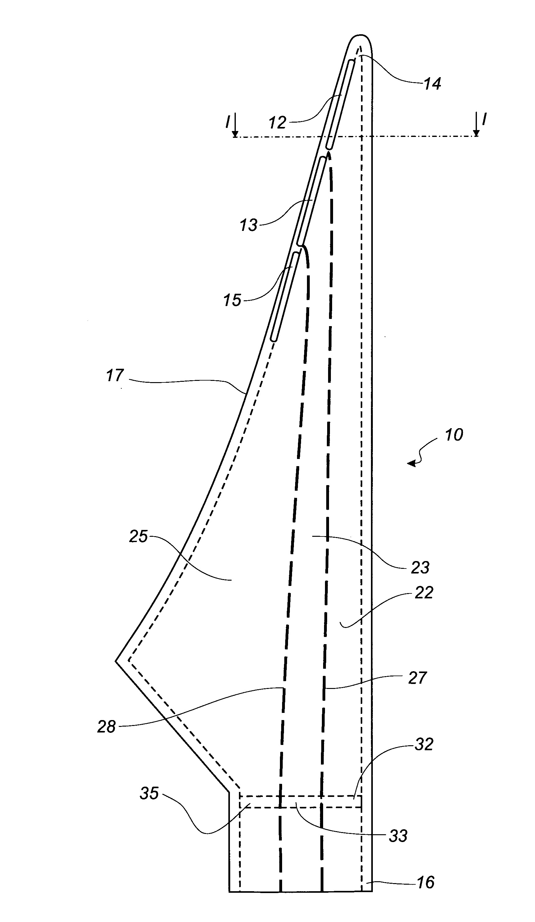
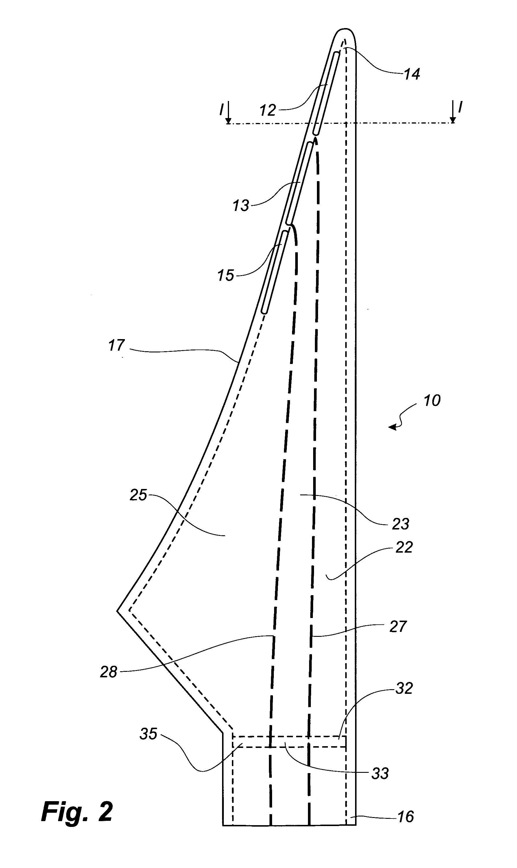
[0044]FIG. 2 shows a schematic view of a wind turbine blade according to the invention. The blade 10 comprises three elongated slots 12, 13, 15. A first slot 12 is placed near the tip 14 of the blade. The first slot is connected to a first internal cavity 22 or first air reservoir, which thereby can communicate with the exterior of the blade. A first valve means 32 is arranged within the first cavity 22. A second slot 13 is placed adjacent the first slot 12. The second slot 13 is connected to a second internal cavity 23 or second air reservoir, which thereby can communicate with the exterior of the blade. A second valve means 33 is arranged within the second cavity 23. A third slot 15 is placed adjacent the third slot 15. The third slot 15 is connected to a third internal cavity 25 or third air reservoir, which thereby can communicate with the exterior of the blade. A third valve means 35 is arranged within the third cavity 25. The first 22 and the second 23 cavity are separated by ...

third embodiment

[0051]FIG. 5 shows a blade 10′″ according to the invention. Instead of slots, the lift-regulating means are formed by groups of holes 42, 43, 45, 52, 53, 55, so that a first longitudinally extending zone comprises a group of first holes 42 and a group of second holes 52, a second longitudinally extending zone comprises a group of first holes 43 and a group of second holes 53, and a third longitudinally extending zone comprises a group of first holes 45 and a group of second holes 55.

[0052]The first groups of holes and second groups of holes can be connected to separate air reservoirs or tubes. Thereby, it is possible to reduce the lift to a first setting by emitting air through the first group of holes, reduce the lift to a second setting by emitting air through the second group of holes, and to a third setting by emitting air through both group of holes. Thus, it is possible to reduce the lift gradually in the different longitudinally extending zones.

[0053]However, the groups of ho...


PUM


Abstract

A blade (10) for a wind turbine rotor with a hub is described. The blade extends in a longitudinal direction along a longitudinal axis and having a root area (16) closest to the hub and a tip region furthest away from the hub. The blade (10) along at least a portion of the longitudinal direction of the blade has an envelope, which defines an airfoil profile having, in normal operation, a pressure side (20) and a suction side (19), and further having a leading edge (18) and a trailing edge (17), which edges define an airfoil chord line extending between them. The blade (10) comprises adjustable lift-regulating means extending in the longitudinal direction of the blade (10), and activating means by means of which the lift-regulating means can be adjusted and thus alter the aerodynamic properties of the blade (10). The lift-regulating means are adapted and arranged so that by activation of the activating means, the lift can be reduced in a zone extending in the longitudinal direction of the blade (10) from a first position in proximity to the blade tip (14) to a second position between the first position and the root area (16) and this second position being variable in the longitudinal direction of the blade. The lift-regulating means are formed of at least one slot (12, 13, 15) or a number of holes (42, 43, 45, 52, 53, 55) arranged in at least one longitudinally extending zone, thereby allowing an interior cavity (22, 23, 25) of the blade (10) to communicate with the exterior. The lift-regulating means are adjustable by means of one or more activating means to regulate the amount of air emitted from the interior cavity (22, 23, 25) to the exterior to alter the aerodynamic properties of the blade (10).

Description

TECHNICAL FIELD [0001]The present invention relates to a blade for a wind turbine rotor with a hub, the blade extending in a longitudinal direction along a longitudinal axis and having a root area closest to the hub and a tip region furthest away from the hub, the blade along at least a portion of the longitudinal direction of the blade having an envelope, which defines an airfoil profile having, in normal operation, a pressure side and a suction side, and further having a leading edge and a trailing edge, which edges define an airfoil chord line extending between them, the blade including adjustable lift-regulating means extending in the longitudinal direction of the blade, and activating means by means of which the lift-regulating means can be adjusted and thus alter the aerodynamic properties of the blade, the lift-regulating means being adapted and arranged so that by activation of the activating means, the lift can be reduced in a zone extending in the longitudinal direction of...

Claims


Application Information

Patent Timeline
IPC IPC(8): F03D7/02F03D1/06
CPCF03D1/0633F03D7/022F03D7/0244F05B2240/30F05B2260/901Y02E10/723F05B2270/32F05B2270/324F05B2270/331Y02E10/721F05B2270/1011Y02E10/72
Inventor BOVE, STEFANOGRABAU, PETER
Owner LM GLASSFIBER
Why Eureka
Try Eureka