Belt driving apparatus and recording apparatus

a technology of driving apparatus and recording apparatus, which is applied in the direction of typewriters, printing, gearing, etc., can solve the problems of limited number of driven pulleys, and achieve the effect of smooth and precise transportation and enhancing the recording quality of the recording apparatus

Inactive Publication Date: 2010-01-21
SEIKO EPSON CORP
View PDF13 Cites 16 Cited by
  • Summary
  • Abstract
  • Description
  • Claims
  • Application Information

AI Technical Summary

Benefits of technology

[0010]An advantage of some aspects of the invention is that it provides a belt driving apparatus that reduces the possibility of tooth jumping by securing a winding angle of an endless belt necessary for a drive pulley regardless of conversion of the rotational direction of a drive motor or a start operation from a stationary state to a rapid reverse direction, and a recording apparatus including the belt driving apparatus.
[0012]According to the first aspect of the invention, since the winding angle maintaining member for maintaining the winding angle of the endless belt with respect to the drive pulley is provided in the vicinity of the drive pulley on a downstream side, a change in the winding angle of the endless belt with respect to the drive pulley is prevented even when the rotational direction of the drive motor is converted or the stopped drive motor is rapidly rotated backward. Therefore, even when the initial tension of the endless belt by the tension pulley is reduced, the endless belt can be transported properly without causing tooth jumping, thereby decreasing the load applied to an output shaft of the drive motor and enabling the drive motor to be properly driven and controlled.
[0013]Specifically, high acceleration / deceleration control of the endless belt and high-precision transport to a high degree can be obtained and the drive motor can be driven at a low power. In addition, the teeth of the endless belt can be made smaller and the transport sound of the endless belt can be reduced, thereby enabling more precise feeding of the endless belt.
[0017]According to the third aspect of the invention, since the winding angle maintaining member is formed such that a surface of the winding angle maintaining member opposite to the outer peripheral surface of the endless belt has a guide shape along the path of the endless belt at a withdrawal position where the endless belt wound on the drive pulley is at a large distance from the drive pulley, the endless belt can be maintained in a wide range, thereby making the winding angle of the endless belt with respect to the drive pulley more stable and realizing proper transport of the endless belt.
[0019]According to the fourth aspect of the invention, in addition to an increase in the winding angle of the endless belt with respect to the drive pulley, since a change in the tension of the endless belt can be absorbed by the cushion operation due to the urging force of a tension pulley similar to the tension pulley installed on the upstream side of the drive pulley, thereby realizing smooth transport of the endless belt with a greater pursuing degree.
[0021]The fifth aspect of the invention can show the same operations and effects as the first to fourth aspects of the invention. A single drive motor drives a transport drive roller and a discharge drive roller, thereby enabling smooth and precise transport in the transport direction and the return direction of the recording medium and additionally enhancing the recording quality of the recording apparatus.

Problems solved by technology

However, the belt driving apparatus of JP-A-2006-77900 has only one driven pulley that can be driven by one drive motor, and the number of driven pulleys is limited.

Method used


Image

  • Belt driving apparatus and recording apparatus
  • Belt driving apparatus and recording apparatus
  • Belt driving apparatus and recording apparatus

Examples


first embodiment

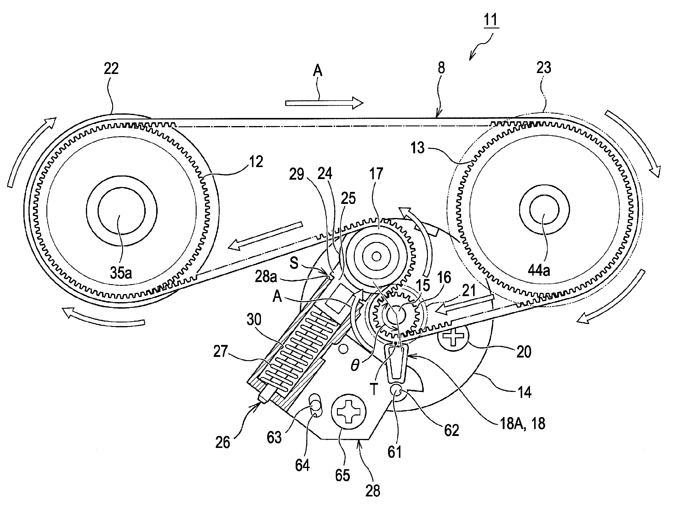
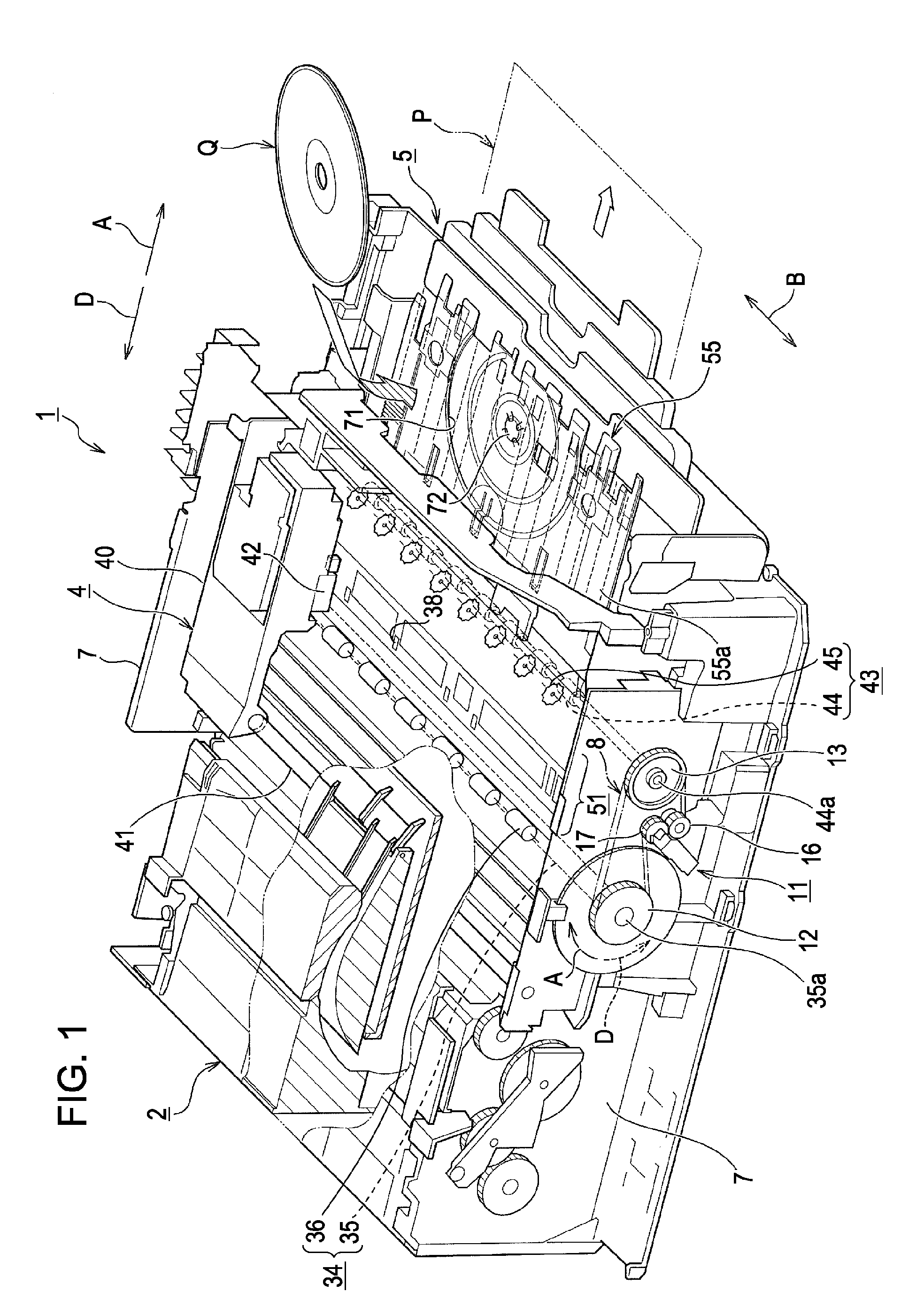
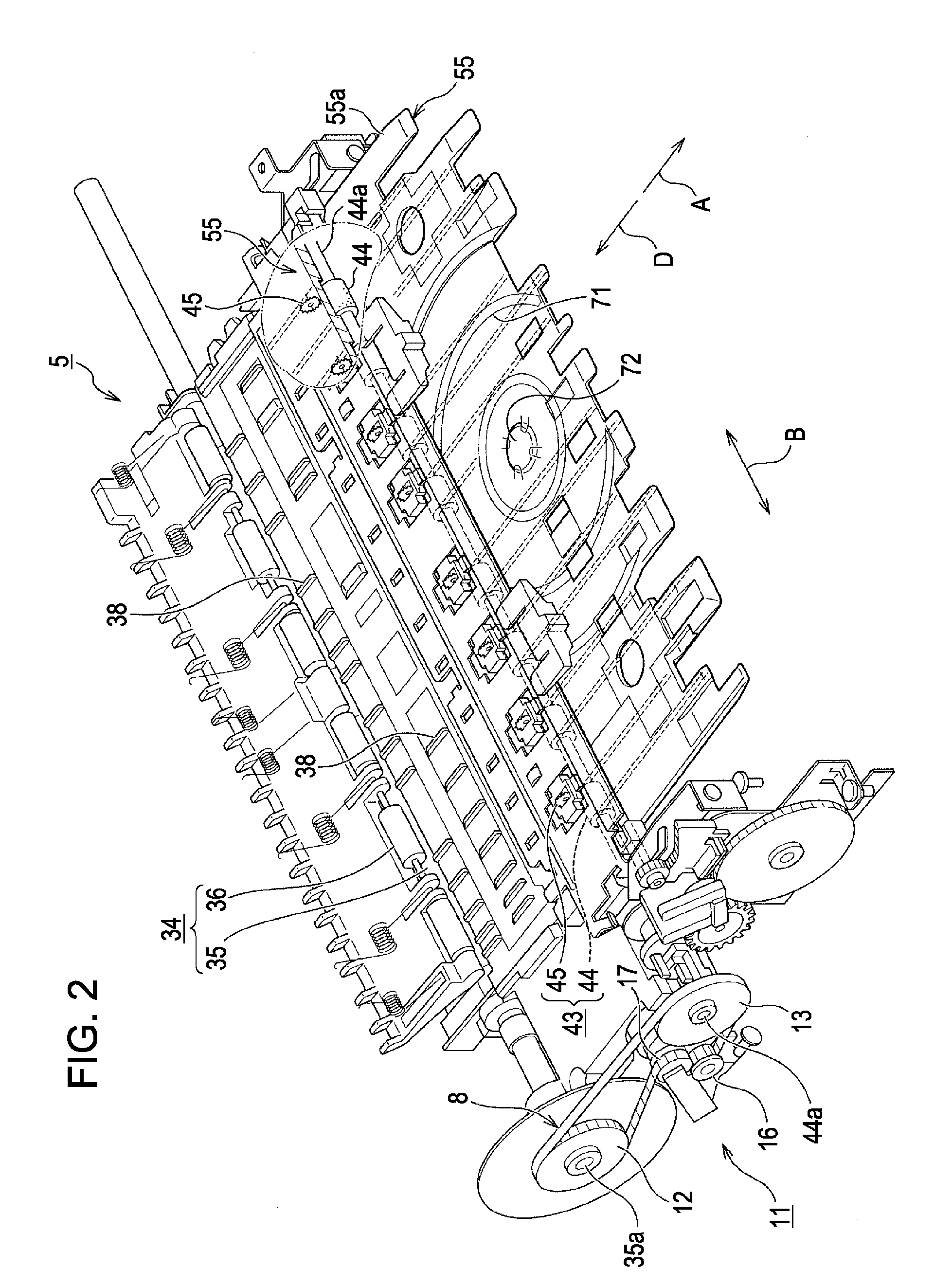
[0045]Hereinafter, the structure of a belt driving apparatus 11 that can be applied as a power transmitting apparatus in the transport apparatus 5 for a recording medium of the inkjet printer 1 according to an embodiment of the invention will be described in detail with reference to the accompanying drawings below. In the specification, an upstream side of the drive pulley 16 means an “upstream side” of the drive pulley 16 along the transport direction of the endless belt 8 when the drive motor 14 is rotated in the backward direction D, and a “downstream side” of the drive pulley 16 means a downstream side of the drive pulley 16 along the transport direction of the endless belt 8 when the drive motor 14 is rotated forward.

[0046]FIG. 3 is a side view of a belt driving apparatus disposed in the outer region of the side frame of the inkjet printer according to an embodiment of the invention. FIG. 4 is a side view of a forward rotation of the belt driving apparatus according to the embo...

second embodiment

[0061]The belt driving apparatus 11 and the recording apparatus 1 that applies the belt driving apparatus 11 as a power transmitting apparatus in a transport apparatus 5 for a recording medium basically have the above-described structures, but partial modifications and eliminations may be made without departing from the spirit or scope of the invention.

[0062]FIG. 7 is a side view of a belt driving apparatus where the configuration of the winding angle maintaining member is made different according to another embodiment of the invention. That is, as illustrated in the belt driving apparatus 11A in FIG. 7, the winding angle maintaining member 18 may have a guide member 18B as shown in the figure. The winding angle maintaining member 18 is formed such that a surface of the winding angle maintaining member 18 opposite to the outer peripheral surface of the endless belt 8 has a guide shape along the path of the endless belt 8 at a withdrawal position where the endless belt 8 wound on the...

third embodiment

[0064]FIG. 8 is a side view of a belt driving apparatus where the configuration of the winding angle maintaining member is made different according to still another embodiment of the invention. As illustrated in the belt driving apparatus 11B of FIG. 8, the winding angle maintaining member 18 may have a guide pulley 18C. The guide pulley 18C is rotatably attached using a swing reference shaft 61 extending from the motor bracket 19 to the outside, has a contact point T on a circumference whose center is the swing reference shaft 61 as in the belt driving apparatus 11 of FIGS. 3 to 6, and an aperture between the outer peripheral surface of the drive pulley 16 and the contact point T is maintained constant regardless of the swing angle of the tension holder 28. The belt driving apparatus 11B having the guide pulley 18C can show the same operation and effect as the belt driving apparatus 11 of FIGS. 3 to 6.


PUM


Abstract

A belt driving apparatus includes: a drive pulley that is attached to an output shaft of a drive motor and has teeth formed on the outer peripheral surface thereof; a driven pulley that is spaced apart from the drive pulley; an endless belt that is wound between the drive pulley and the driven pulley and is configured of a timing belt; a tension pulley that is provided on an upstream side in the vicinity of the drive pulley and comes in contact with the outer peripheral surface of the endless belt on an upstream side to apply tension to the endless belt; and a winding angle maintaining member that is provided on a downstream side in the vicinity of the drive pulley and on the side of the outer peripheral surface of the belt to maintain the winding angle of the endless belt with respect to the drive pulley.

Description

BACKGROUND[0001]1. Technical Field[0002]The present invention relates to a belt driving apparatus that includes a drive pulley that is attached to an output shaft of a drive motor and has teeth formed on the outer peripheral surface thereof; a driven pulley that is spaced apart from the drive pulley and has teeth formed on the outer peripheral surface thereof; an endless belt that is wound between the drive pulley and the driven pulley and is a timing belt having teeth on the inner peripheral surface thereof; and a tension pulley that is provided on an upstream side of the drive pulley in the vicinity of the drive pulley and comes in contact with the outer peripheral surface of the endless belt on an upstream side of the endless belt to apply tension to the endless belt; and a recording apparatus, such as a facsimile machine or a copying machine, which includes the belt driving apparatus.[0003]2. Related Art[0004]Hereinafter, an inkjet printer will be described as an example of a re...

Claims


Application Information

Patent Timeline
Patent Type & Authority Applications(United States)
IPC IPC(8): F16H7/02F16H7/18F16H7/08B41J23/02
CPCB41J3/4071B41J11/0035B41J23/02F16H2007/0897F16H7/18F16H2007/0806F16H7/1263
Inventor MINEMURA, HIDEFUMI
Owner SEIKO EPSON CORP
Why Eureka
Try Eureka