Transmission for motor and controlling device thereof

Active Publication Date: 2010-01-21
MBI CO LTD
View PDF6 Cites 14 Cited by
  • Summary
  • Abstract
  • Description
  • Claims
  • Application Information

AI Technical Summary

Benefits of technology

[0021]As described above, the transmission for the motor according to the present invention provides a one-way output irrespective of the rotational direction of an input and can perform deceleration or acceleration of the output when the direction of the input is changed. In the present invention, the motor embedded in the transmission is a brushless motor (BLDC) of a relatively high torque, and hence, c

Problems solved by technology

In addition, the automatic transmission does not have a restraining means, such as the clutch, and automatically changes the speed according to a pressure change or the like of an output side.
However, the manual transmission according to a prior art has a problem in that it is inconveni

Method used


Image

  • Transmission for motor and controlling device thereof
  • Transmission for motor and controlling device thereof
  • Transmission for motor and controlling device thereof

Examples


Embodiment Construction

[0030]Reference will be now made in detail to the preferred embodiment of the present invention with reference to the attached drawings.

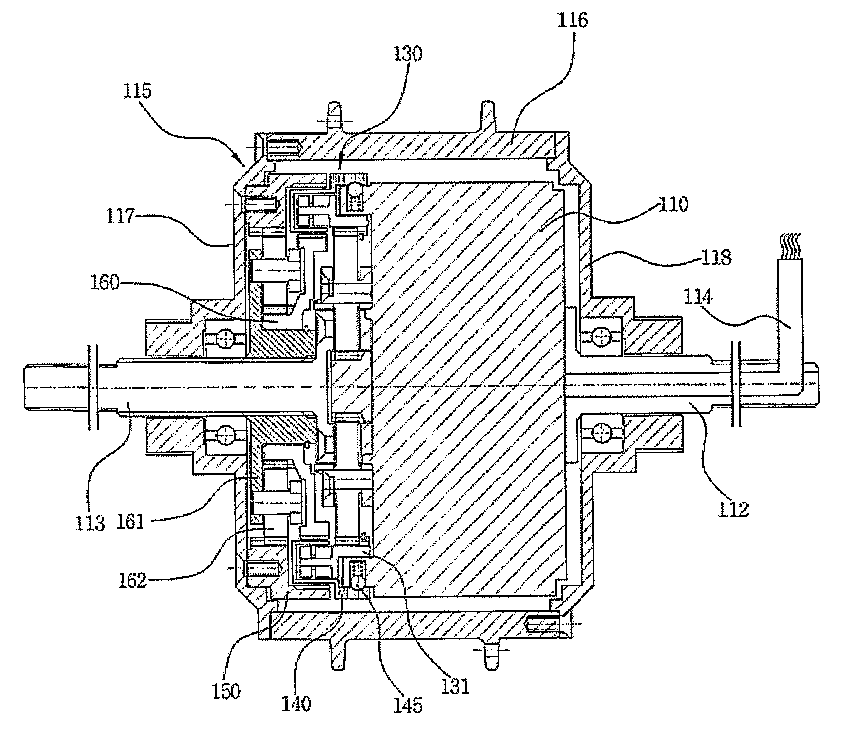
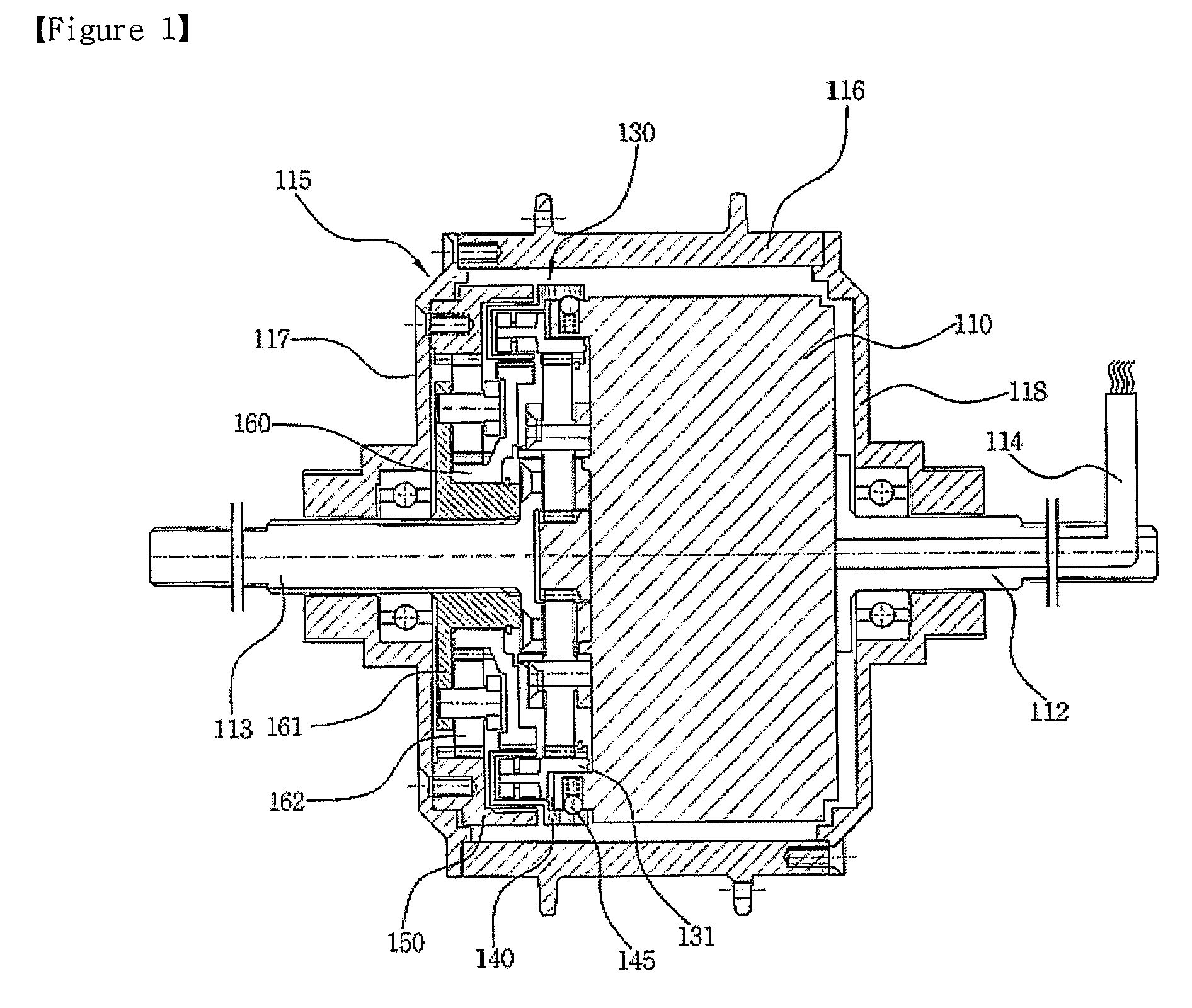
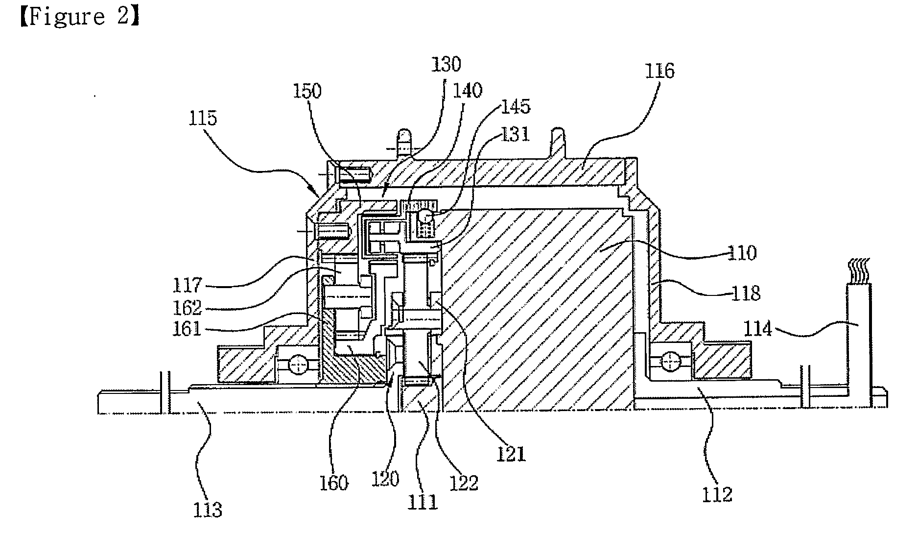
[0031]FIGS. 1 to 3 are sectional views of a transmission for a motor according to the present invention, wherein FIGS. 1 and 2 illustrate the transmission applied to an inner rotor type motor, and FIG. 3 illustrates the transmission applied to an outer rotor type motor.

[0032]Preferably, FIGS. 1 to 3 illustrate a motor for a motorcycle, but the present invention can be applied to other various devices, for instance, transportation machines such as vehicles, industrial machines such as electromotive tools or the like, and toys.

[0033]As shown in FIGS. 1 and 2, the present invention includes: a motor 110 supplied with power to rotate; an output cover 115 adapted to surround the outside of the motor 110 and rotated by a rotational force of the motor 110; a first fixed shaft 113 extending to a side of the output cover 115; a second fixed shaft 112 extendi...


PUM


Abstract

Disclosed therein is a transmission, which is adapted to have a deceleration structure while generating an output in the same direction as when a motive power is rotated forwardly when the motive power is rotated reversely. The transmission includes: a motor having a driving shaft; an output cover adapted to surround the outside of the motor and rotated by receiving a rotational force of the motor; fixed shafts adapted to extend toward both sides of the output cover; and a transmission formed between the driving shaft and the output cover. The transmission is selectively connected according to the rotational direction of the driving shaft to thereby provide an output at a constant speed or a reduced speed only in a predetermined direction. The transmission provides a constant speed output in the forward direction since the driving shaft and the output cover are directly connected to each other when the driving shaft is rotated forwardly, but provides a decelerated output in the forward direction since a reduction planetary gear is geared between the driving shaft and the output cover when the driving shaft is rotated reversely. In addition, a controlling device for automatically controlling the transmission for the motor according to a load applied to the output side is also provided.

Description

TECHNICAL FIELD [0001]The present invention relates to a transmission for a motor, and more particularly, to a transmission, which is adapted to perform either acceleration or deceleration when the rotational direction of a motor is changed, and a controlling device adapted to automatically control the transmission of the motor.BACKGROUND ART [0002]In general, a transmission is a device for accelerating or decelerating a motive power.[0003]Such a transmission is coupled to a motor driving shaft to thereby automatically or manually change the speed of the motor power. In case of the manual transmission, a clutch is located between the motive power and the transmission to thereby achieve a speed change in a state where the motive power to the transmission is interrupted. In addition, the automatic transmission does not have a restraining means, such as the clutch, and automatically changes the speed according to a pressure change or the like of an output side.[0004]However, the manu...

Claims


Application Information

Patent Timeline
IPC IPC(8): B60W10/04F16H3/00F16H57/08F16H3/60F16H3/66H02K7/10
CPCB62M6/65B62M7/12Y10T74/19172Y10T477/68F16H3/005F16H2200/0034F16H2200/2005F16H2200/2007F16H3/44F16H1/28
Inventor JUNG, TAE-JINYOO, HYUK
Owner MBI CO LTD
Why Eureka
Try Eureka